DFI LanParty NF3 VDimm Mod |
|
5V as VDimm-source Mod
Datasheet of the MOSFET: http://www.samhop.com.tw/pdf/SD(DU)9916.pdf
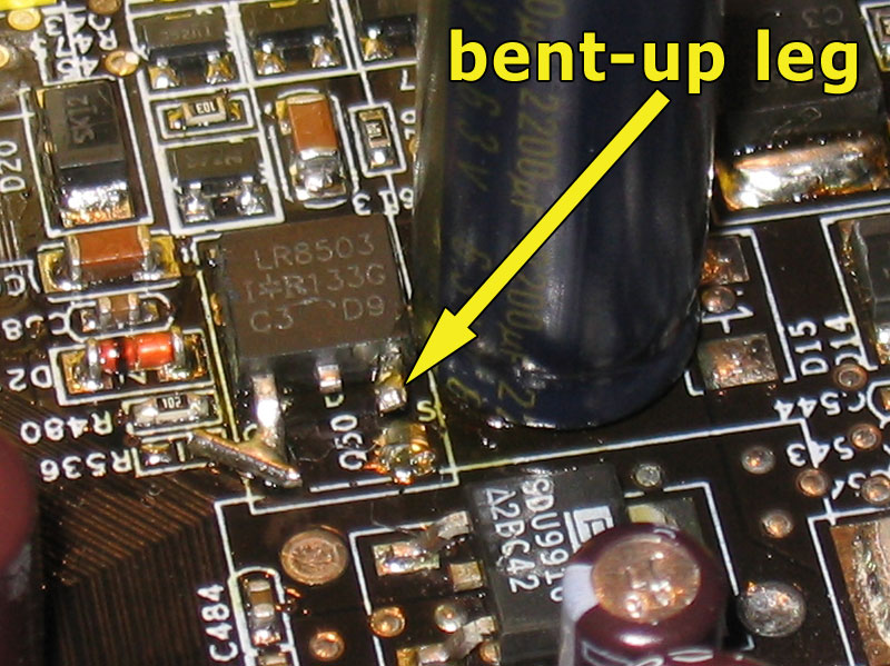
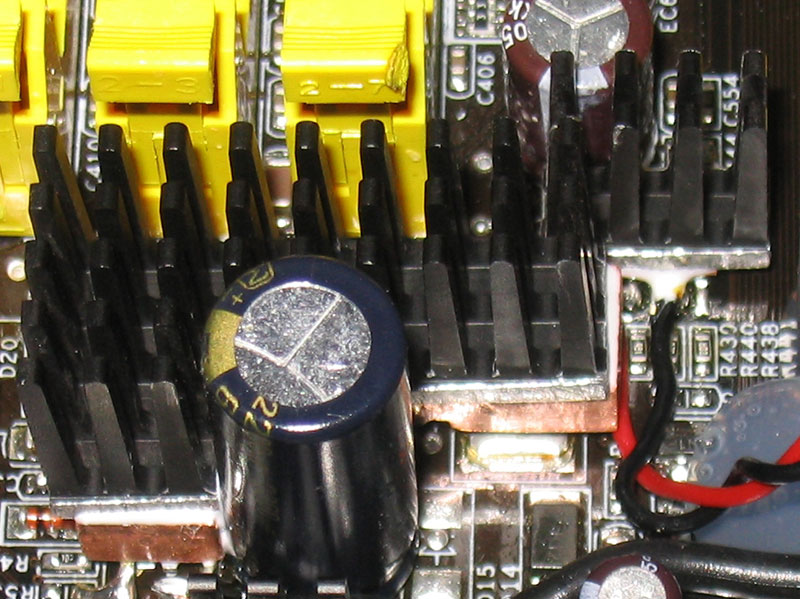
The mod is quite simple in theory. You have to bend up the MOSFET's source pin to disconnect it from the motherboard and then solder a 5V wire to it. This MOSFET is Q50 which is located directly under the DIMM slots. Don’t wonder why your MOSFET looks different than the one in my pictures, I had to replace mine, so don’t worry. The source pin is even marked with an "S" on the PCB. A good way to get 5V is from the 5V pin of the ATX power connector.
While this sounds easy, unfortunately it is a bit harder in practice. The problem is that it's nearly impossible to just remove the MOSFET's source-pin from the solder pad on the board, without damaging the MOSFET or breaking the pin.
The solution to this problem is to remove the whole MOSFET, bend up the source-pin and then solder it in again. After that, you are ready to finish the mod.
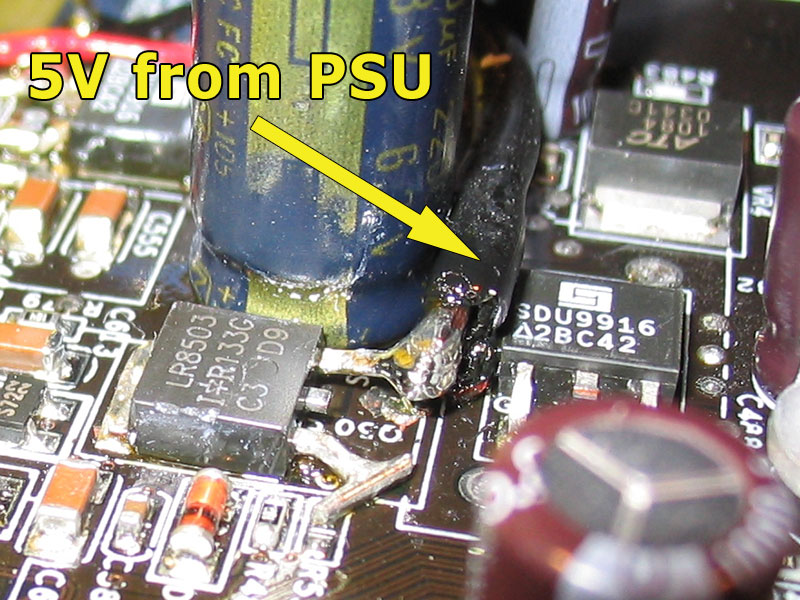
What you have to do then, is get a thick wire (there will be quite some amps going through it, when running good RAM at high volts and high clocks, that's why a thin wire won't be enough) and locate the 5V contacts on the backside of the board, where the ATX connector of your power supply gets connected to your board. Now you can just solder one end of the cable to the two 5V contacts and the other end to the bent up source-pin (MOSFET "Q50"). Make sure that the pin is bent up high enough, so there is no contact to the old solder-pad (which is connected to the 3.3V-line via the motherboard) when the cable is soldered in.
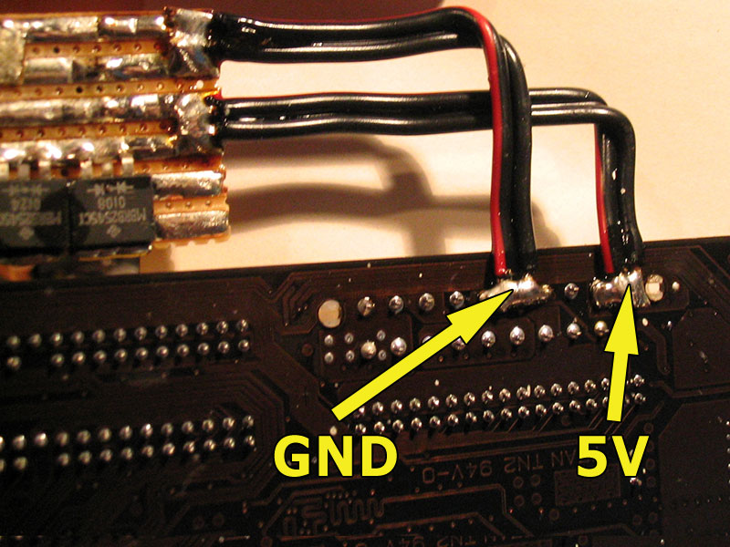
Optionally you can do it like I did and put in a capacitor (the ground connection in the picture is needed for the capacitor only. I used a 1000µF 6.3V low ESR cap). The capacitor filters the voltage a bit.
Another optional tweak is to add some diodes between the 5V source (ATX connector) and the MOSFET source-pin. The diodes drop the input voltage to the MOSFET slightly (~0.7 V, diodes are in parallel). This helps reduce the heat dissipated from the MOSFET. Make sure you use diodes with at least 10A, so that they won't blow under load.


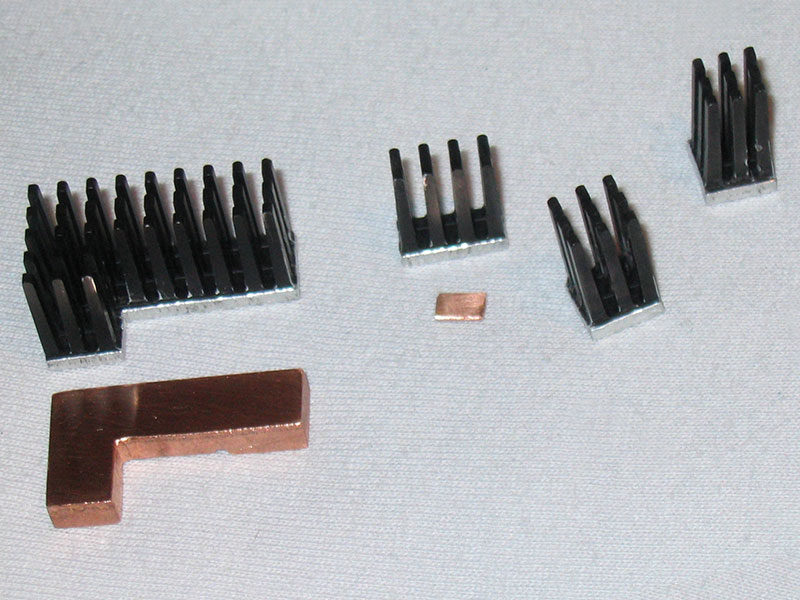
One rather bad side effect of this mod though, is that the MOSFET "Q38" gets hotter than before (hotter than with the standard 3.3V based VDimm supply; the MOSFETs are rated for up to 150°C, but that’s only the MOSFETs; the surrounding components wouldn’t like the hot climate :) ). I advise you not to run the modded board without additional cooling for at least this one MOSFET (“Q38”). In fact it would be best if you put heatsinks on the MOSFETS "Q50" and "Q38", in order to play it safe.

I had some problems while trying to figure out the perfect way to do this mod. I removed and soldered in MOSFETS and capacitors several times and after some successful tries, the MOSFETs' solder pads suddenly came off the board, i.e. they were broken. Lucky as I am, I had tested all the solder pads for connections before and knew what they were connected to. That's why you see more connections than just the cable connected to the MOSFET’s source-pin. In the process of finishing the mod, I had to fix all MOSFET solder pads, as they were all broken. Here are all the fixes, in case you should damage one of your solder pads, too:


Apr 25th, 2024 15:27 EDT
change timezone
Latest GPU Drivers
New Forum Posts
- Black screen after muting (4)
- What software are you using to monitor CPU temps during gaming session? (8)
- What phone you use as your daily driver? And, a discussion of them. (1479)
- Alphacool CORE 1 CPU block - bulging with danger of splitting? (14)
- Will a RTX 4070 TI super bottleneck a Ryzen 9 7950X3D? (59)
- What are you playing? (20527)
- How to check flatness of CPUs and coolers - INK and OPTICAL INTERFERENCE methods (111)
- Ghetto Mods (4321)
- Random blue screen from winload.efi error (0xc000000e) (2)
- Meta Horizon OS (20)
Popular Reviews
- Fractal Design Terra Review
- Thermalright Phantom Spirit 120 EVO Review
- Corsair 2000D Airflow Review
- Minisforum EliteMini UM780 XTX (AMD Ryzen 7 7840HS) Review
- ASUS GeForce RTX 4090 STRIX OC Review
- NVIDIA GeForce RTX 4090 Founders Edition Review - Impressive Performance
- ASUS GeForce RTX 4090 Matrix Platinum Review - The RTX 4090 Ti
- MSI GeForce RTX 4090 Suprim X Review
- MSI GeForce RTX 4090 Gaming X Trio Review
- Gigabyte GeForce RTX 4090 Gaming OC Review
Controversial News Posts
- Sony PlayStation 5 Pro Specifications Confirmed, Console Arrives Before Holidays (116)
- NVIDIA Points Intel Raptor Lake CPU Users to Get Help from Intel Amid System Instability Issues (106)
- Windows 11 Now Officially Adware as Microsoft Embeds Ads in the Start Menu (102)
- AMD "Strix Halo" Zen 5 Mobile Processor Pictured: Chiplet-based, Uses 256-bit LPDDR5X (101)
- US Government Wants Nuclear Plants to Offload AI Data Center Expansion (98)
- AMD's RDNA 4 GPUs Could Stick with 18 Gbps GDDR6 Memory (85)
- Developers of Outpost Infinity Siege Recommend Underclocking i9-13900K and i9-14900K for Stability on Machines with RTX 4090 (85)
- Windows 10 Security Updates to Cost $61 After 2025, $427 by 2028 (84)