DFI LanParty NFII Ultra B Voltmods |
|
VCore-Mod
Datasheet of the chip:http://www.intersil.com/data/fn/fn4765.pdf
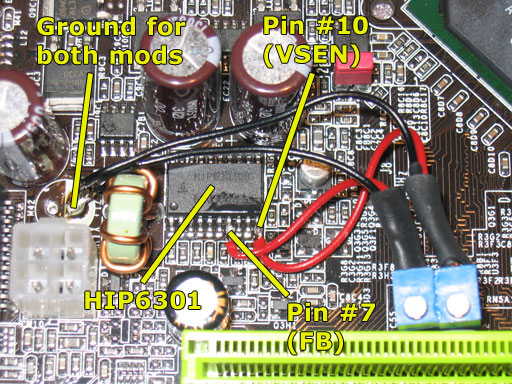
Connect the middle pin of the 50K potentiometer to Pin #7 (FB) of the HIP6301 chip and then connect the outer pin of the potentiometer to Ground.
Pin #9 of the HIP6301 is a Ground pin, but we will need to solder a cable to the next Pin #10 for the OVP-Mod. I didn't like the idea of soldering two cables right next to each other. That would've been very hard, and why do it the hard way, if there's an easier way right around the corner. For Ground I just used the Ground point from a left-empty solder-pad ("EC18"), where DFI had planned to put a capacitor, but cancelled that idea obviously (solder point in the area that is marked white, is GROUND). Use that point as Ground for both the VCore- and the OVP-mod, it will have no negative impact on the mods.
OVP-Mod
Same chip, so no new datasheet link needed (still HIP6301).The OverVoltage Protection-Mod is only needed, if you are going to run a VCore higher than 2.0V.
As I already mentioned above, the OVP-Mod involves connecting a 50K potentiometer from Pin #10 of the HIP6301 chip to Ground.
Just connect the outer pin of the potentiometer to the Ground point mentioned above (left-empty solder-pad, not far from the HIP6301 chip). Then connect the middle pin of the pot to Pin #10 (VSEN). Well, that's it and you've finished the VCore and OVP mods.
Picture for both VCore- and OVP-Mod
Apr 24th, 2024 23:42 EDT
change timezone
Latest GPU Drivers
New Forum Posts
- im new to throttelstop and i think i messed it up by copying others any hints would be very much aprreciated (1)
- Aida64 cache mem OC (7)
- I am getting artifacting when I change Windows security settings. Is my GPU failing, or is this just a Windows issue? (10)
- Is there a technical reason that Windows 11 doesn't have built into it battery charge limitation? (42)
- (Anti) SFF fun house (347)
- Cinebench crashed my PC. My Wi-Fi stopped working, and I keep getting a "Please wait" screen when I boot up my PC. (30)
- The TPU UK Clubhouse (24783)
- Sharing experience with MSI RTX 3070 vBIOS update to enable Resizable Bar with MB Z490 (2)
- Share your AIDA 64 cache and memory benchmark here (2915)
- Will a RTX 4070 TI super bottleneck a Ryzen 9 7950X3D? (58)
Popular Reviews
- Fractal Design Terra Review
- Thermalright Phantom Spirit 120 EVO Review
- Corsair 2000D Airflow Review
- Minisforum EliteMini UM780 XTX (AMD Ryzen 7 7840HS) Review
- ASUS GeForce RTX 4090 STRIX OC Review
- NVIDIA GeForce RTX 4090 Founders Edition Review - Impressive Performance
- ASUS GeForce RTX 4090 Matrix Platinum Review - The RTX 4090 Ti
- MSI GeForce RTX 4090 Suprim X Review
- MSI GeForce RTX 4090 Gaming X Trio Review
- Gigabyte GeForce RTX 4090 Gaming OC Review
Controversial News Posts
- Sony PlayStation 5 Pro Specifications Confirmed, Console Arrives Before Holidays (116)
- NVIDIA Points Intel Raptor Lake CPU Users to Get Help from Intel Amid System Instability Issues (106)
- AMD "Strix Halo" Zen 5 Mobile Processor Pictured: Chiplet-based, Uses 256-bit LPDDR5X (101)
- US Government Wants Nuclear Plants to Offload AI Data Center Expansion (98)
- Windows 10 Security Updates to Cost $61 After 2025, $427 by 2028 (84)
- Developers of Outpost Infinity Siege Recommend Underclocking i9-13900K and i9-14900K for Stability on Machines with RTX 4090 (84)
- TechPowerUp Hiring: Reviewers Wanted for Motherboards, Laptops, Gaming Handhelds and Prebuilt Desktops (78)
- AMD's RDNA 4 GPUs Could Stick with 18 Gbps GDDR6 Memory (73)