DFI LanParty NFII Ultra B Voltmods |
|
VDimm-Mod
Datasheet of the chip:http://www.semtech.com/pdf/sc2616.pdf
The middle pin of the 100K potentiometer normally would need to be connected to SC2616's Pin #1 (FB). But as the chip has very tiny legs/contacts, that would be nearly impossible to do with normal equipment. Thus we trace pin #1 to a SMD/SMT resistor just next to the chip (marked in the pic). Now you need to connect the potentiometer's middle pin to the side of that resistor, facing the greenish capacitor next to it, as seen in the pic. After that you have to connect the outer pin of the potentiomter to Ground. Just like when doing the VCore-/OVP-Mod, I used an empty solder pad ("EC57") as Ground. Again, it was planned to be used for a cap and was then left empty in the final product (see the pic for details). Measuring point for Vdimm is on the second mosfet from the left, under the RAM slots. Make sure to take a look at the pic for the correct leg, as it depends on how your board is placed on the table. That way, you can't go wrong.

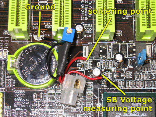
Southbridge-VMod
For that last mod, again a 50K poti is needed. To supply more voltage to the southbridge chipset, it's required to remove the SMD/SMT resistor "R151", next to "VR4" (looking like a mosfet, right next to the second PCI slot, counting from the top). You just desolder that resistor and connect the upper solder-point, which is now empty (after having removed the SMD/SMT resitor), to the middle pin of the 50K potentiometer. Afterwards, you connect the outer pin of the potentiometer to a Ground point nearby. I used the solder-pad ("EC32") next to the battery, right under PCI-slot #3.The measuring point for the southbridge voltage is the upper contact of the capacitor "EC42", right next to the other soldering-points.
Apr 25th, 2024 18:42 EDT
change timezone
Latest GPU Drivers
New Forum Posts
- Alphacool CORE 1 CPU block - bulging with danger of splitting? (16)
- Core PL1 + GPU PL1 + Ring EDP OTHER (7)
- How to check flatness of CPUs and coolers - INK and OPTICAL INTERFERENCE methods (112)
- Best SSD for system drive (78)
- Which new games will you be buying? (314)
- TPU's Nostalgic Hardware Club (18464)
- Post your Cinebench 2024 score (450)
- Ubuntu 24.04 LTS released (2)
- Dell Workstation Owners Club (3054)
- im new to throttelstop and i think i messed it up by copying others any hints would be very much aprreciated (2)
Popular Reviews
- Fractal Design Terra Review
- Thermalright Phantom Spirit 120 EVO Review
- Corsair 2000D Airflow Review
- Minisforum EliteMini UM780 XTX (AMD Ryzen 7 7840HS) Review
- ASUS GeForce RTX 4090 STRIX OC Review
- NVIDIA GeForce RTX 4090 Founders Edition Review - Impressive Performance
- ASUS GeForce RTX 4090 Matrix Platinum Review - The RTX 4090 Ti
- MSI GeForce RTX 4090 Suprim X Review
- MSI GeForce RTX 4090 Gaming X Trio Review
- Gigabyte GeForce RTX 4090 Gaming OC Review
Controversial News Posts
- Sony PlayStation 5 Pro Specifications Confirmed, Console Arrives Before Holidays (117)
- Windows 11 Now Officially Adware as Microsoft Embeds Ads in the Start Menu (106)
- NVIDIA Points Intel Raptor Lake CPU Users to Get Help from Intel Amid System Instability Issues (106)
- AMD "Strix Halo" Zen 5 Mobile Processor Pictured: Chiplet-based, Uses 256-bit LPDDR5X (101)
- US Government Wants Nuclear Plants to Offload AI Data Center Expansion (98)
- AMD's RDNA 4 GPUs Could Stick with 18 Gbps GDDR6 Memory (87)
- Developers of Outpost Infinity Siege Recommend Underclocking i9-13900K and i9-14900K for Stability on Machines with RTX 4090 (85)
- Windows 10 Security Updates to Cost $61 After 2025, $427 by 2028 (84)