techPowerUp! Forums

Go Back   techPowerUp! Forums > Hardware > Cases, Modding & Electronics

Reply
 
Thread Tools
Old Jun 16, 2010, 11:55 AM   #1
de.das.dude
3500 Posts
 
de.das.dude's Avatar
 
Join Date: Jun 2010
Location: Wild Wild East
Posts: 4,585 (4.26/day)
Thanks: 2,337
Thanked 1,342 Times in 919 Posts
Send a message via Skype™ to de.das.dude

System Specs

Make your own fan speed control under $1 USD

This will help you make those little somethings like home made fan speed controls, etc, that you have to put in the PCI bracket space.

I FINISHED the fan speed control at last!!


Here are the dimensions for the PCI bracket along with a picture(poor quality, sorry).
(no, the scientific calculator at the top of the pic wasn't used, i used it as a paper weight)


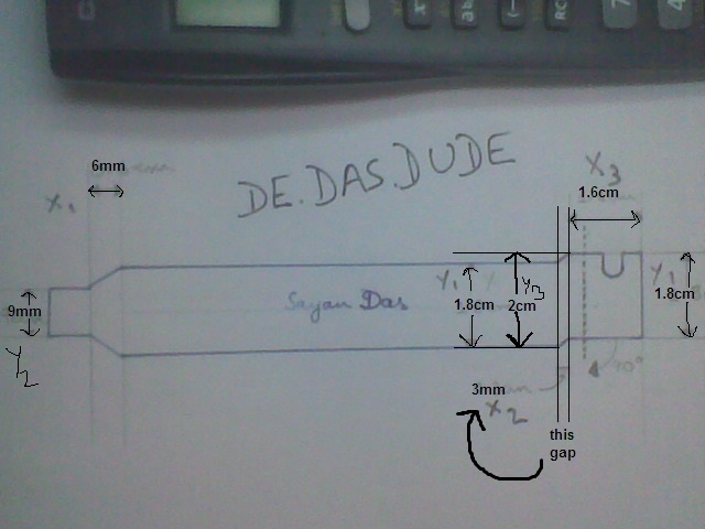
all dimensions X are along horizontal(along x-axis)
all dimensions Y are along vertical(along y-axis)

total length from left to the dotted line is 13.2cm.
X1 = 6mm
X2 = 3mm
X3 = 1.6cm

Y1 = 1.8cm
Y2 = 9mm
Y3 = 2.0cm

*The dotted line is where we turn the part on the left at right angles, while pulling it toward us....get it? its faintly visible in the pic.


Here are some pics of the aluminium bracket I made


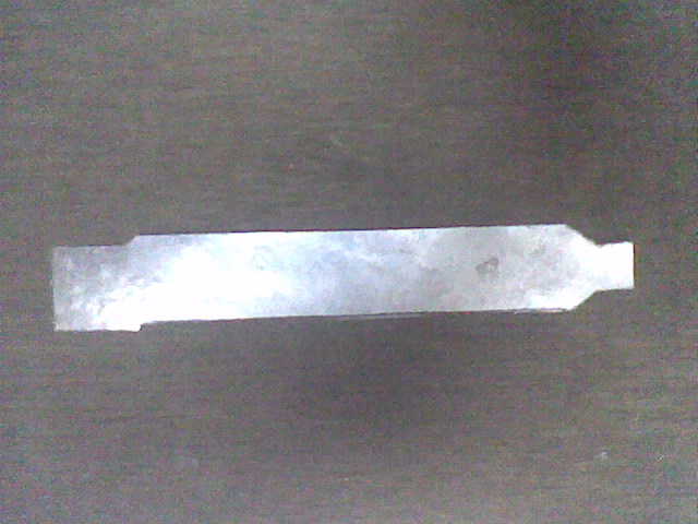
The bracket after cutting out:


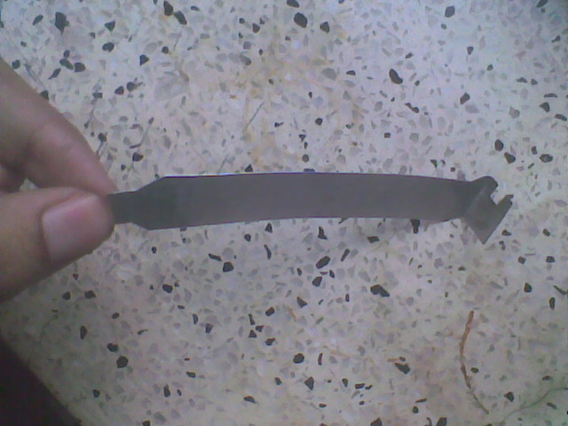
Cutting out the screw hole and bending it:


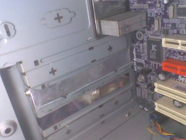
This is the cover that guards the opening:


i bent it in half and stuck it to the bracket to reinforce... You may stick it without bending in half, though.
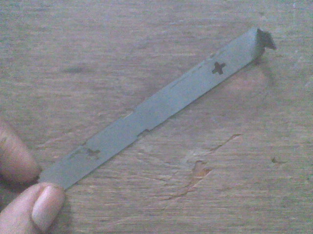
the final result:

only fixing the potentiometer is left.


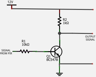
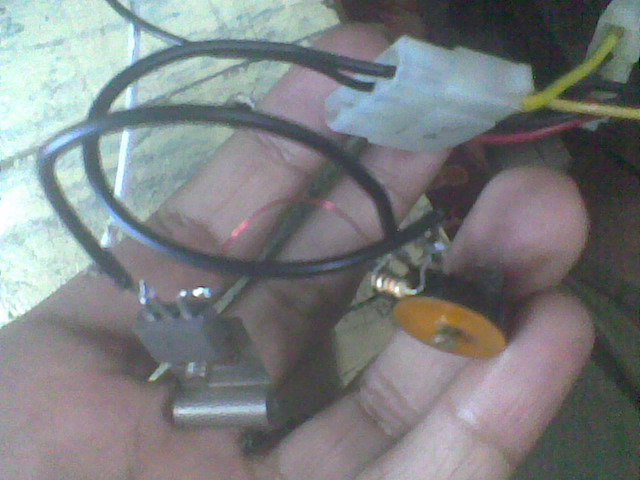
Here's the package of my test circuit. ALWAYS REMEMBER TO FOLLOW THE GOLDEN RULE OF TRANSISTORS: INPUT THROUGH BASE ANN AMPLIFIED OUT OF THE COLLECTOR.


Its time to move on to the real deal!
This is the layout of my printed board circuit:

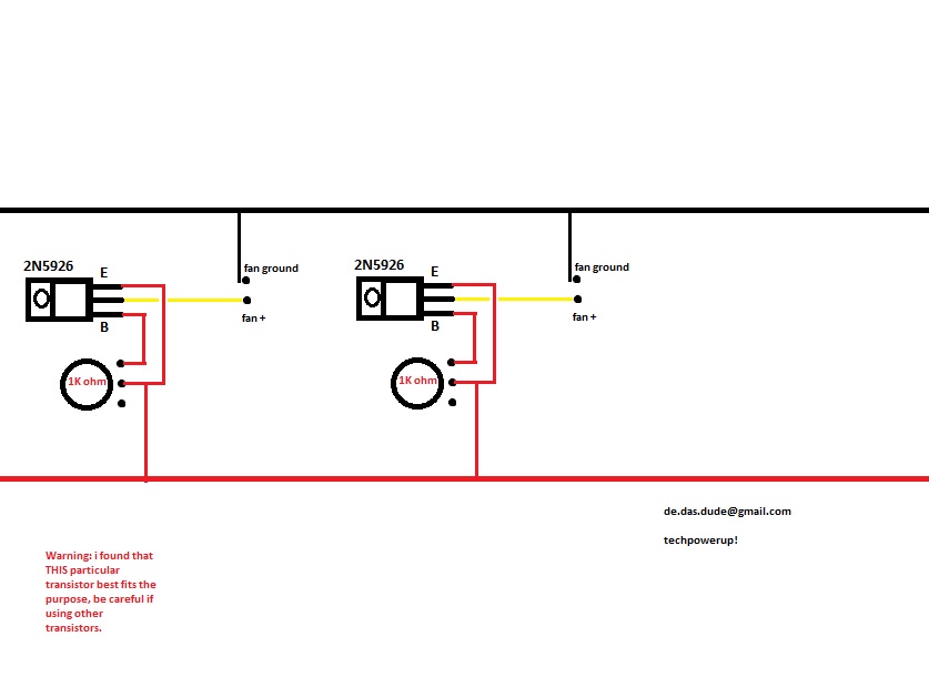
notice how the two individual fan controllers are simply copy paste!


This is the circuit nicely soldered on a piece of 24 pin print board.


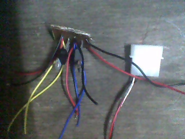
After attaching the output jacks for the two sets of fans, the potentiometers and mounting them on the bracket
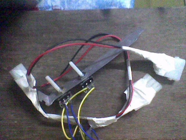


and ...... ACTION!


Does it work??
Yes, yes it does!! And that too for any load you put across it. This means you can run with multiple fans in parellel!! This controls fan speed between 100% and 25-30%.

THIS is the best way 'cause it cost less than $1 for the whole thing!!

Only draw back is that for 2 or 3 pin fans the speed control isnt uniform, but on the other hand, not enough to notice


LED UPDATE:-
The LED is basically connected to the fan(s) in parallel, through a particular amount of resistance (or else the LED will(may) burn up).

Here's how to calculate the resistance using ohm's law.
first lets say your LED is rated "v" volts and "i" amperes.
so now i've simplified a formula for you
resistance = (12-v)/(i+current rating of fan)


another EDIT:-

For insulating the underside of the PCB, you can use your mom's or sis's nail polish. easy to apply and easy to remove. + this is better than Liquid electrical tape!!!

njoy!

ps:- dont forget the thanks!
Attached Thumbnails
Click image for larger version

Name:	Image000.jpg
Views:	6240
Size:	63.3 KB
ID:	36313   Click image for larger version

Name:	bracket cover, flattened and bent in half.jpg
Views:	103
Size:	72.7 KB
ID:	36336   Click image for larger version

Name:	the bracket after cutting out.jpg
Views:	4934
Size:	76.4 KB
ID:	36337   Click image for larger version

Name:	after cutting out the screw hole and bending it.jpg
Views:	4902
Size:	76.0 KB
ID:	36338   Click image for larger version

Name:	the bracket cover on the chassis.jpg
Views:	4887
Size:	67.8 KB
ID:	36339  

Click image for larger version

Name:	the bracket in place.jpg
Views:	4895
Size:	72.5 KB
ID:	36340   Click image for larger version

Name:	this is easy and small!!.jpg
Views:	4863
Size:	72.8 KB
ID:	36380   Click image for larger version

Name:	Circuit on board.jpg
Views:	4864
Size:	46.1 KB
ID:	36430   Click image for larger version

Name:	printed board circuit.jpg
Views:	4759
Size:	36.5 KB
ID:	36431   Click image for larger version

Name:	after attaching the output jacks.jpg
Views:	4772
Size:	65.4 KB
ID:	36432  

Click image for larger version

Name:	in action.jpg
Views:	4752
Size:	69.0 KB
ID:	36433  

Last edited by de.das.dude; Jul 9, 2010 at 06:49 AM.
de.das.dude is offline  
Reply With Quote
The Following 6 Users Say Thank You to de.das.dude For This Useful Post:
Old Jun 16, 2010, 11:57 AM   #2
Aleksander
2000 Posts
 
Aleksander's Avatar
 
Join Date: Dec 2009
Posts: 3,028 (2.39/day)
Thanks: 648
Thanked 280 Times in 228 Posts

System Specs

That looks really great! Thank you
Aleksander is offline  
Reply With Quote
Old Jun 16, 2010, 12:10 PM   #3
de.das.dude
3500 Posts
 
de.das.dude's Avatar
 
Join Date: Jun 2010
Location: Wild Wild East
Posts: 4,585 (4.26/day)
Thanks: 2,337
Thanked 1,342 Times in 919 Posts
Send a message via Skype™ to de.das.dude

System Specs

I think i will use Aluminium sheet, you guys got any better material?
de.das.dude is offline  
Reply With Quote
Old Jun 16, 2010, 12:21 PM   #4
1freedude
200 Posts
 
1freedude's Avatar
 
Join Date: Nov 2007
Posts: 452 (0.22/day)
Thanks: 207
Thanked 120 Times in 90 Posts

System Specs

Carbon Fiber!
1freedude is offline  
Reply With Quote
Old Jun 16, 2010, 12:29 PM   #5
de.das.dude
3500 Posts
 
de.das.dude's Avatar
 
Join Date: Jun 2010
Location: Wild Wild East
Posts: 4,585 (4.26/day)
Thanks: 2,337
Thanked 1,342 Times in 919 Posts
Send a message via Skype™ to de.das.dude

System Specs

@ 1freedude
lol!! i need to get a factory to have them fabricated the way i like!
de.das.dude is offline  
Reply With Quote
Old Jun 16, 2010, 12:32 PM   #6
scaminatrix
2000 Posts
 
scaminatrix's Avatar
 
Join Date: Mar 2010
Location: By the Channel Tunnel, Kent, England
Posts: 2,432 (2.06/day)
Thanks: 1,834
Thanked 802 Times in 672 Posts

System Specs

Just when I ordered 3 Zalman Fan-mates!
Thanks .dude can't wait to see this finished...
__________________
MKMods Tribute Rig - the Power of the Community
HeatWare
Did I make the 2,000,000th post?
If an 8 Core can hit 6Ghz with an H100 i'll post pictures of my hot fiance - Pestilence
Every day I come to this site, I am reminded why I come to this site every day!!! - Iggster
scaminatrix is offline  
Reply With Quote
Old Jun 16, 2010, 05:01 PM   #7
de.das.dude
3500 Posts
 
de.das.dude's Avatar
 
Join Date: Jun 2010
Location: Wild Wild East
Posts: 4,585 (4.26/day)
Thanks: 2,337
Thanked 1,342 Times in 919 Posts
Send a message via Skype™ to de.das.dude

System Specs

here is how I calculated the resisance setup to power my 3V LED.

From experience i know i need two resistances, with one resistance connected in parell to my LED.

suppose resistances are "x" and "y" in series.
since my voltage across the series combo is 12V.
current through them is 12/(x+y) which is equal to to "i" (say)

now, i need 3V across one of the resistors(lets take "y"),
so for "y"; i*y=3

also across "x" volts is x*i=12-y*i

therefore we get the ratio of x:y as 3:1!
i can use a 3 ohm and a 1 ohm resistance!


took me 30sec to do, and 2min to type it here. LOL
de.das.dude is offline  
Reply With Quote
Old Jun 16, 2010, 06:10 PM   #8
ty_ger
75 Posts
 
ty_ger's Avatar
 
Join Date: Jun 2008
Location: Pacific Coast
Posts: 85 (0.05/day)
Thanks: 20
Thanked 14 Times in 11 Posts

System Specs

Quote:
Originally Posted by de.das.dude View Post
here is how I calculated the resisance setup to power my 3V LED.

From experience i know i need two resistances, with one resistance connected in parell to my LED.

suppose resistances are "x" and "y" in series.
since my voltage across the series combo is 12V.
current through them is 12/(x+y) which is equal to to "i" (say)

now, i need 3V across one of the resistors(lets take "y"),
so for "y"; i*y=3

also across "x" volts is x*i=12-y*i

therefore we get the ratio of x:y as 3:1!
i can use a 3 ohm and a 1 ohm resistance!


took me 30sec to do, and 2min to type it here. LOL
What are you going to use to control the fan speed?

Placing the load accross a potentiometer is of course the easiest method of controlling the speed, but is not very efficient.

I suppose for this application with low voltage and low load, efficiency isn't too important, but something a bit more exotic with pulse-width modulation would be pretty nifty.
ty_ger is offline  
Reply With Quote
Old Jun 16, 2010, 06:14 PM   #9
de.das.dude
3500 Posts
 
de.das.dude's Avatar
 
Join Date: Jun 2010
Location: Wild Wild East
Posts: 4,585 (4.26/day)
Thanks: 2,337
Thanked 1,342 Times in 919 Posts
Send a message via Skype™ to de.das.dude

System Specs

Quote:
Originally Posted by ty_ger View Post
What are you going to use to control the fan speed?

Placing the load accross a potentiometer is of course the easiest method of controlling the speed, but is not very efficient.

I suppose for this application with low voltage and low load, efficiency isn't too important, but something a bit more exotic with pulse-width modulation would be pretty nifty.
haha, sure, i'll go the easy way. As i stated i dont exactly have a lot of time. i'll have to finish it all in one day.

But nice idea! i'll keep it in mind.
de.das.dude is offline  
Reply With Quote
Old Jun 16, 2010, 06:25 PM   #10
ty_ger
75 Posts
 
ty_ger's Avatar
 
Join Date: Jun 2008
Location: Pacific Coast
Posts: 85 (0.05/day)
Thanks: 20
Thanked 14 Times in 11 Posts

System Specs

Quote:
Originally Posted by de.das.dude View Post
haha, sure, i'll go the easy way. As i stated i dont exactly have a lot of time. i'll have to finish it all in one day.

But nice idea! i'll keep it in mind.
Just for future reference, this looks like a pretty cool and easy way to do something similar in the future:
http://www.robotroom.com/PWM.html


I have made a RC inverter myself before so I know that it is viable, but i used two transistors instead of an IC and therefore my output current capability was different. It appears that the one in the guide I just linked to is only capable of 25mA output which is far too little. But the general design is perfect for a fan controller.

I have mine lying around somewhere and a schematic I drew up, but I don't remember where I put it. It was quite similar to this though:

^Just an example; I don't necessarily recommend this method. Obvioulsy the design would have to be altered. The design explained in the robotroom.com article seems easier and is well explained.

Here is a pretty interesting part of the artice I linked to above:
http://www.robotroom.com/PWM4.html

Basically, it explains why you would want to use PWM in some situations instead of a potentiometer and also shows how you can get over the current limitations of the circuit (25mA) by supplying the inverter output to another transistor that can handle a greater capacity.


Last edited by ty_ger; Jun 16, 2010 at 07:02 PM.
ty_ger is offline  
Reply With Quote
The Following 2 Users Say Thank You to ty_ger For This Useful Post:
Old Jun 16, 2010, 06:32 PM   #11
de.das.dude
3500 Posts
 
de.das.dude's Avatar
 
Join Date: Jun 2010
Location: Wild Wild East
Posts: 4,585 (4.26/day)
Thanks: 2,337
Thanked 1,342 Times in 919 Posts
Send a message via Skype™ to de.das.dude

System Specs

Oh an inverter? i have done one, simpler though(just a simple tank circuit based one) for my high school.(class 12)

my dad knows these stuff too.
Also the control i'll make tomorrow will be made from stuff he had bought himself previously around 6-10yrs ago!!
anyway thanks again!!
de.das.dude is offline  
Reply With Quote
Old Jun 16, 2010, 06:43 PM   #12
de.das.dude
3500 Posts
 
de.das.dude's Avatar
 
Join Date: Jun 2010
Location: Wild Wild East
Posts: 4,585 (4.26/day)
Thanks: 2,337
Thanked 1,342 Times in 919 Posts
Send a message via Skype™ to de.das.dude

System Specs

when i was thinking on the complex side, i just thought about using the PWM oin of my CPU fan to regulate. i cant understand what u are talking about.

amd the fans i'll be using is 2pin, not very complex!!

I read the article at the link u gave,
its just the same thing, done in a hard way!!! LOL!! long live 10K pot.!!

Last edited by de.das.dude; Jun 16, 2010 at 06:50 PM.
de.das.dude is offline  
Reply With Quote
Old Jun 16, 2010, 09:44 PM   #13
ty_ger
75 Posts
 
ty_ger's Avatar
 
Join Date: Jun 2008
Location: Pacific Coast
Posts: 85 (0.05/day)
Thanks: 20
Thanked 14 Times in 11 Posts

System Specs

Quote:
Originally Posted by de.das.dude View Post
when i was thinking on the complex side, i just thought about using the PWM oin of my CPU fan to regulate. i cant understand what u are talking about.
The pulsating DC output would be supplied to the fan. Changing "off/on time" (duty cycle) of the power will cause the fan to vary speed accordingly.

Quote:
amd the fans i'll be using is 2pin, not very complex!!
Exactly. All you need is to provide the power from the PWM to the positive side of the fan and the other wire off the fan goes to ground. A PWN fan controller of this style is perfect for simple applications.

Quote:
I read the article at the link u gave,
its just the same thing, done in a hard way!!! LOL!! long live 10K pot.!!
The advantage of PWM is that setting the fan controller potentiometer at 50% with a PWM circuit would make the fan go exactly 50% of full speed no matter how large or small of a fan you use. With just a potentiometer with no PWM control, a small fan will need to be turned down close to 0% to slow down and a large fan will need to be turned up close to 100% to speed up.

In other words, depending on the size of the fan and the amount of air restriction before and after the fan, setting the potentiometer of your fan control to 50% without a PWM may make the fan barely turn or spin close to full speed. It will be unpredictable.
ty_ger is offline  
Reply With Quote
Old Jun 17, 2010, 04:59 AM   #14
de.das.dude
3500 Posts
 
de.das.dude's Avatar
 
Join Date: Jun 2010
Location: Wild Wild East
Posts: 4,585 (4.26/day)
Thanks: 2,337
Thanked 1,342 Times in 919 Posts
Send a message via Skype™ to de.das.dude

System Specs

Ya, thats why i have to choose the pot carefully.

And in this pulsating voltage the motor will bw half the time on and half the times off. So unless i can supply 24V, i wont get the full speed of the fan, but only 50%.

Last edited by de.das.dude; Jun 17, 2010 at 05:09 AM.
de.das.dude is offline  
Reply With Quote
Old Jun 17, 2010, 05:36 AM   #15
ty_ger
75 Posts
 
ty_ger's Avatar
 
Join Date: Jun 2008
Location: Pacific Coast
Posts: 85 (0.05/day)
Thanks: 20
Thanked 14 Times in 11 Posts

System Specs

Quote:
Originally Posted by de.das.dude View Post
And in this pulsating voltage the motor will bw half the time on and half the times off. So unless i can supply 24V, i wont get the full speed of the fan, but only 50%.
Well, not really. Turning the potentiometer all the way down would make the output be effectively almost zero where there would be infrequent pusles of voltage to the motor. Turning the potentiometer all the way up would make the output to the fan effectively almost 100 since there would only be very infrequent breaks in power to the fan.

It doesn't have to only do 50%. I just used 50% as an example. Turning the potentiometer changes the duty cycle of the power output. Duty cycle pretty much means the ratio of off time compared to on time. Adjusting the potentiometer would change the ratio between them so that all the way down would be off most the time with infrequent pulses of on while turning the potentiometer up would do the opposite and the duty cycle ratio would change accordingly for any speed in between.

As you see above, the chip in the circuit can only handle between 2 and 6 volts. You would have to supply 5v from the power supply to run the PWM circuit and have the modulated output run to another final transistor connected to 12v would switch on and off accordingly and provide power to the fan.
ty_ger is offline  
Reply With Quote
The Following User Says Thank You to ty_ger For This Useful Post:
Old Jun 17, 2010, 05:42 AM   #16
de.das.dude
3500 Posts
 
de.das.dude's Avatar
 
Join Date: Jun 2010
Location: Wild Wild East
Posts: 4,585 (4.26/day)
Thanks: 2,337
Thanked 1,342 Times in 919 Posts
Send a message via Skype™ to de.das.dude

System Specs

No maan! it works on 6V, the motor is 12V!! get it?

i found a 12V hex inverter IC
IC HEX INVERT BUFF/CONV 16-DIP - CD4009UBE
de.das.dude is offline  
Reply With Quote
Old Jun 17, 2010, 06:08 AM   #17
de.das.dude
3500 Posts
 
de.das.dude's Avatar
 
Join Date: Jun 2010
Location: Wild Wild East
Posts: 4,585 (4.26/day)
Thanks: 2,337
Thanked 1,342 Times in 919 Posts
Send a message via Skype™ to de.das.dude

System Specs

CAN U pm ME THE FULL SCHEMATIC?
de.das.dude is offline  
Reply With Quote
Old Jun 17, 2010, 01:16 PM   #18
ty_ger
75 Posts
 
ty_ger's Avatar
 
Join Date: Jun 2008
Location: Pacific Coast
Posts: 85 (0.05/day)
Thanks: 20
Thanked 14 Times in 11 Posts

System Specs

Quote:
Originally Posted by de.das.dude View Post
No maan! it works on 6V, the motor is 12V!! get it?

i found a 12V hex inverter IC
IC HEX INVERT BUFF/CONV 16-DIP - CD4009UBE
Yeah, the controller would hook up to 5v power from the PSU. Connect the PWM output from the controller to a transistor which switches power on and off to the fan at 12v.

A little adaptation from the original design and here you go:


You would just have to consolidate all of that onto a single circuit board with a 4-pin molex input and a fan header. Route all the wires on the circuit board to make the appropriate connections and provide power input from molex connection to the right places and ground from the molex connection to the right places. Fan header would have 12v on one side directly from molex connector and ground side would go through NPN transistor to ground.


If this stuff isn't making sense to you, ask your dad for advice and see if he sees any sense in what I am saying.

Quote:
Originally Posted by de.das.dude View Post
No maan! it works on 6V, the motor is 12V!! get it?

i found a 12V hex inverter IC
IC HEX INVERT BUFF/CONV 16-DIP - CD4009UBE
You would have to find information about that IC yourself since it isn't likely layed out the same as in the schematic above. The method I posted would work as it would take 5v from the PSU to run the controller and switch on and off 12v to the fan controller through a power transistor.

Last edited by ty_ger; Jun 17, 2010 at 01:25 PM.
ty_ger is offline  
Reply With Quote
The Following User Says Thank You to ty_ger For This Useful Post:
Old Jun 17, 2010, 02:08 PM   #19
de.das.dude
3500 Posts
 
de.das.dude's Avatar
 
Join Date: Jun 2010
Location: Wild Wild East
Posts: 4,585 (4.26/day)
Thanks: 2,337
Thanked 1,342 Times in 919 Posts
Send a message via Skype™ to de.das.dude

System Specs

@ ty ger,
i told u to give the schematic so that other people viewing this thread can use it if the want.

and i wont use bread board. i will use a printed board.
de.das.dude is offline  
Reply With Quote
Old Jun 17, 2010, 07:02 PM   #20
ty_ger
75 Posts
 
ty_ger's Avatar
 
Join Date: Jun 2008
Location: Pacific Coast
Posts: 85 (0.05/day)
Thanks: 20
Thanked 14 Times in 11 Posts

System Specs

Quote:
Originally Posted by de.das.dude View Post
@ ty ger,
i told u to give the schematic so that other people viewing this thread can use it if the want.

and i wont use bread board. i will use a printed board.
Well, that diagram above is kind of a hybrid. It isn't really a true schatic, but it should get the job done.

I just bought a house and am in the process of moving stuff in and whatnot, so I am not so sure how much time I will have. But if I have time, I will try making one of these assuming I can easily get ahold of the proper components locally. Then I can test it and take pictures of it. I would like to get a molex connector and a fan header connector, but I am not sure how easy those will be found locally. I guess I do have spare molex cables and fan adapters that I can steal the parts off of.
ty_ger is offline  
Reply With Quote
Old Jun 17, 2010, 07:05 PM   #21
de.das.dude
3500 Posts
 
de.das.dude's Avatar
 
Join Date: Jun 2010
Location: Wild Wild East
Posts: 4,585 (4.26/day)
Thanks: 2,337
Thanked 1,342 Times in 919 Posts
Send a message via Skype™ to de.das.dude

System Specs

AhaH! after going through the "semiconductor devices an digital electronics" chapter from my class 12 once again, i get everything.

Instead of the inverter IC i think it is better to use a single 12V transistor to make a not gate.

that will minimize the space and also the need for amplifying the voltage to 12V. although i'm having residual doubts whether the current output will be around 35mA(my fans is 35mA) and whether we will get a pulse.

Last edited by de.das.dude; Jun 17, 2010 at 07:21 PM.
de.das.dude is offline  
Reply With Quote
Old Jun 17, 2010, 11:17 PM   #22
ty_ger
75 Posts
 
ty_ger's Avatar
 
Join Date: Jun 2008
Location: Pacific Coast
Posts: 85 (0.05/day)
Thanks: 20
Thanked 14 Times in 11 Posts

System Specs

Quote:
Originally Posted by de.das.dude View Post
AhaH! after going through the "semiconductor devices an digital electronics" chapter from my class 12 once again, i get everything.

Instead of the inverter IC i think it is better to use a single 12V transistor to make a not gate.

that will minimize the space and also the need for amplifying the voltage to 12V. although i'm having residual doubts whether the current output will be around 35mA(my fans is 35mA) and whether we will get a pulse.
Given that the fan consumes 35mA at 12v I did some calculations and concluded that when the fan is operating at full speed, its internal resistance is around 343 Ohms.

Given that information, I was able to conclude that with a 1K Ohm resistor in series with the fan such as you have drawn above, the voltage drop accross that resistor would be roughly 8.94v at full fan speed setting and thus the fan would only be provided with 3.065v for its operation. As you see, this wouldn't do good things for your fan control. The 35mA fan would only be operating at 8.9mA and would be spinning very slow.

On another note, I asked my dad about this stuff a bit. He graduated as an electrical engineer but never made it his profession. Regardless, he seemed to believe that adjusting speed via pulse width would provide more reliable fan operation versus adjusting speed via voltage. What I mean is that he believed the relation to potentiometer adjustment to the observed fan speed behavior would be more linear and predictable by adjusting pulse width instead of adjusting voltage.

He also believed that a fan rated at 12v would operate for a longer period of time without problems if provided with pulses of its rated voltage potential versus running the fan at lower voltage potential than it was rated/designed for. I don't know if there is any truth to that though.
ty_ger is offline  
Reply With Quote
Old Jun 18, 2010, 03:04 AM   #23
ty_ger
75 Posts
 
ty_ger's Avatar
 
Join Date: Jun 2008
Location: Pacific Coast
Posts: 85 (0.05/day)
Thanks: 20
Thanked 14 Times in 11 Posts

System Specs

Well, I checked locally and could not get ahold of the required 74AC14 IC for the diagram above.

While lacking that, I decided to do a proof of concept based on an inverter design I created earlier. After slight modification, here is the final product:


Two transistors connected to RC circuits cause a flip-flop action producting a square wave of varying duty cycle. This square wave output is fed to a NPN transistor which provides low impedance current to the fan.

Here is a video I uploaded to YouTube:
http://www.youtube.com/watch?v=7uQynXcu8Tg

Notice how me stopping the fan didn't cause the voltage to change much. This shows off why the PWM design is cool because varying load doesn't affect the output voltage nearly as much as if you just placed the load in series with a potentiometer. Also by me stopping the fan, you can visually see the effects of the electrical pulses going through the fan.

As I said, this was only a proof of concept and not too much thought was put into it. I am sure that there are things which could be tweaked in order to provide better operating characteristics. For instance, the capacitance accross the fan could be increased from 0.047 microfarads to a higher value in order to filter out more high frequencies introduced by the square wave in order to minimize high frequency buzzing traditionally associated with PWM at low fan speed. I just used the value I used since it was the only capacitor I had handy.

Currently, the final NPN transistor which is operting the fan is turning on when the transistor feeding it is in the off state. It is getting its positive power through the two 1 kilohm resistors. When the second transistor closes, the positive at the base of the final NPN transistor switches from positive to negative and causes the final transistor controlling the fan to shut off. One could try using a PNP transistor placed between the 12v source and the fan instead of an NPN transistor placed between the ground and the fan (as it is currently) to see how that affects the fan characteristics.

Like this:


Notice how swapping the last transistor from NPN to PNP also caused the 47 kilohm and 1 kilohm resistors biasing the potentiometer to also swap position. The reason why they swap and the reason why they aren't of equal value is to limit the lowest fan speed possible (to keep the fan from stalling) and to allow the output voltage to be able to increase up close to the 12v input. If the resistors were the same value, the fan speed could be decreased to the point that it would stall and full fan increase setting would be slower and final output voltage wouldn't come nearly as close to the optimum 12v we desire.

EDIT:
This video explains better than I ever could:
http://pcbheaven.com/circuitpages/High_Frequency_PWM_Fan_Controller/


In case you were wondering, this is the inverter design I based my fan PWM design off of:


The design isn't magnificent and the output isn't very efficient, but it was a fun project nonetheless. The output to the multitap transformer is an unfiltered square wave. Transformers don't really react well to square waves so it would be a good idea to do some filtering ahead of time to round off the corners. But without filtering, the transformer does take some of the edge off at the cost of efficiency losses and a slight buzzing. The potentiometer in this design serves to simply adjust the output frequency.

I really need to do some more tweaking on the above circuit some time. Filtering out the input to the transformer by adding capacitors should help alot by filtering out the square wave to a sawtooth wave. Also, clipping diodes accross the transformer input might help to provide a cleaner output wave.

Last edited by ty_ger; Jun 25, 2010 at 12:42 AM.
ty_ger is offline  
Reply With Quote
Old Jun 19, 2010, 07:57 PM   #24
de.das.dude
3500 Posts
 
de.das.dude's Avatar
 
Join Date: Jun 2010
Location: Wild Wild East
Posts: 4,585 (4.26/day)
Thanks: 2,337
Thanked 1,342 Times in 919 Posts
Send a message via Skype™ to de.das.dude

System Specs

Finally finished it!!!

I got the 74xx14 IC but i did it in the way i said.

i'll update the thread tomorrow morning(for me) with details and pics.
de.das.dude is offline  
Reply With Quote
Old Jun 22, 2010, 12:15 AM   #25
Hockster
200 Posts
 
Hockster's Avatar
 
Join Date: Mar 2010
Location: Edmonton, AB
Posts: 384 (0.33/day)
Thanks: 7
Thanked 101 Times in 71 Posts

System Specs

Wouldn't using a 5.25 bay cover be better? Who wants to reach around the back of their case all the time?
Hockster is offline  
Reply With Quote
The Following User Says Thank You to Hockster For This Useful Post:
Reply


Currently Active Users Viewing This Thread: 1 (0 members and 1 guests)
 
Thread Tools

Posting Rules
You may not post new threads
You may not post replies
You may not post attachments
You may not edit your posts

BB code is On
Smilies are On
[IMG] code is On
HTML code is Off

Forum Jump

Similar Threads
Thread Thread Starter Forum Replies Last Post
how do you make your you fan speed 100% BloodTotal Graphics Cards 10 Dec 25, 2008 04:19 PM
RivaTuner Power User, Setting Your Own Fan Auto Control OrbitzXT Graphics Cards 3 Nov 17, 2007 06:19 AM
How to: make your own STALKER mod Ketxxx Games 0 Oct 27, 2007 01:58 PM
How to make your own phase cooler DaMulta Overclocking & Cooling 2 Jul 16, 2007 10:33 PM
Wheres the temp control and fan speed control section? Nick89 ATITool 6 Jun 3, 2006 09:03 AM


All times are GMT. The time now is 02:20 AM.


Powered by vBulletin® Version 3.8.6
Copyright ©2000 - 2013, Jelsoft Enterprises Ltd.
no new posts