 1
1
Akasa Venom Power 850 W Review
Voltage Regulation, Hold-up Time & Inrush Current »A Look Inside & Component Analysis
Before reading this page, we strongly suggest a look at this article, which will help you understand the internal components of a PSU much better.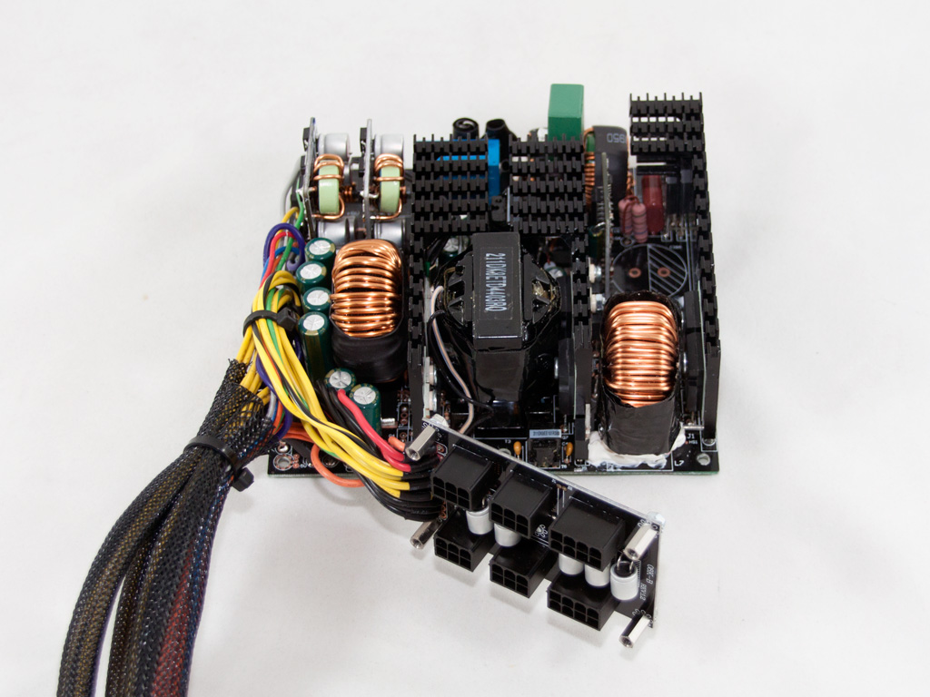

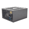
The OEM of this unit is Andyson: the same company that built the first two Venom Power PSUs. Apparently, Akasa liked their work and decided to cooperate with them again for their two high-end Venom PSUs. The results of our test sessions will prove if they made the right choice this time since the last Venom PSU we tested didn't perform so well. The platform used in this PSU surely doesn't include cutting edge technology, but the secondary side does utilize synchronous rectification with two DC-DC converters for the generation of the minor rails.
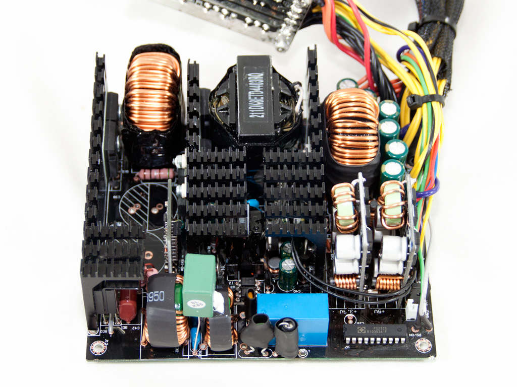
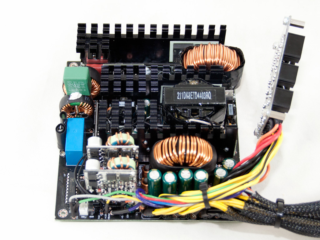
At the rear of the AC receptacle are two Y caps and one X cap. They form the first stage of the transient filter. We find the second stage, which consists of two CM chokes, two Y caps, one X cap, and an MOV, on the main PCB. There is also an NTC thermistor, which provides protection against large inrush currents during start up, and a relay that cuts it off the circuit once the APFC caps are fully charged.

Two bridge rectifiers are used in parallel to provide higher efficiency. Both are bolted onto the primary heatsink.
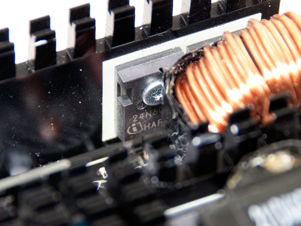


In the APFC, two SPW24N60C3 fets chop the intermediate DC voltage coming from the bridge rectifiers and convert it to constant pulse sequences. Not one but two CREE C3D10060 boost diodes are used in the APFC. This is kind of strange since, usually, only interleaved PFC converters use two boost diodes. Finally, the APFC caps are two parallel Teapos rated at 85°C (420V, 220μF each or 440μF combined).


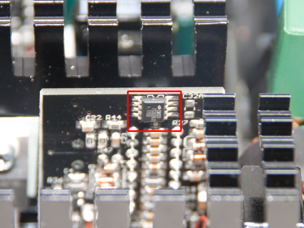
The primary choppers are two SIHG22N60E fets. The combo PFC/PWM controller is housed on a vertical daughter-board and is a Champion CM6800G IC. We were at least expecting the updated CM6802 IC in a Gold PSU, but the main controller is, in this case, supported by a CM03X Green PFC controller for better efficiency.
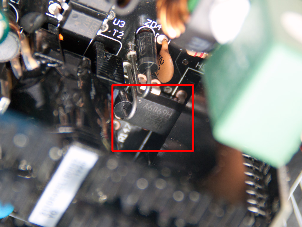
The standby PWM controller is an STR-A6069H IC that is well hidden under the fins of the primary heatsink.


This small vertical PCB houses an SP6019 synchronous rectifier (SR) driver IC that controls the fets which rectify the +12V rail: six IRFB3206 fets.


All filtering caps on the secondary side are provided by Teapo and are labeled at 105°C.

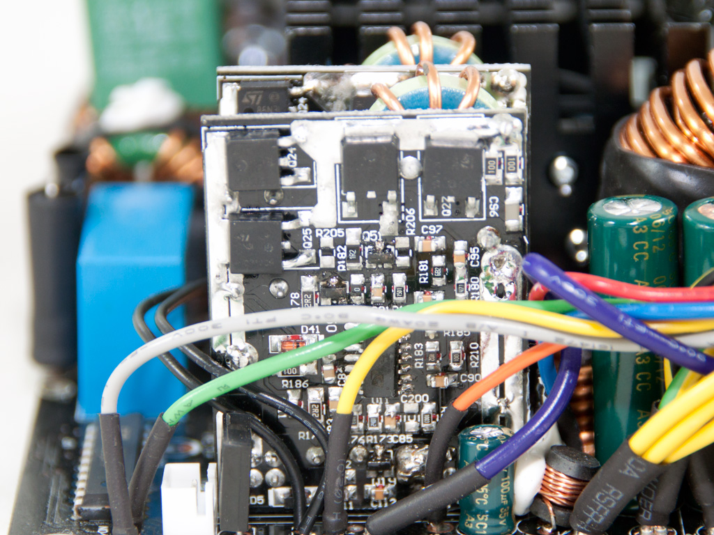
Two VRMs (Voltage Regulation Modules) generate the minor rails. We find four STD85N3LH5 fets and an Anpec APW7073 PWM controller on each VRM.


As you can see, this platform supports four +12V rails and has four current shunts on the component side. During our tests we discovered that the OCP for each rail is set at a little over 40 A.
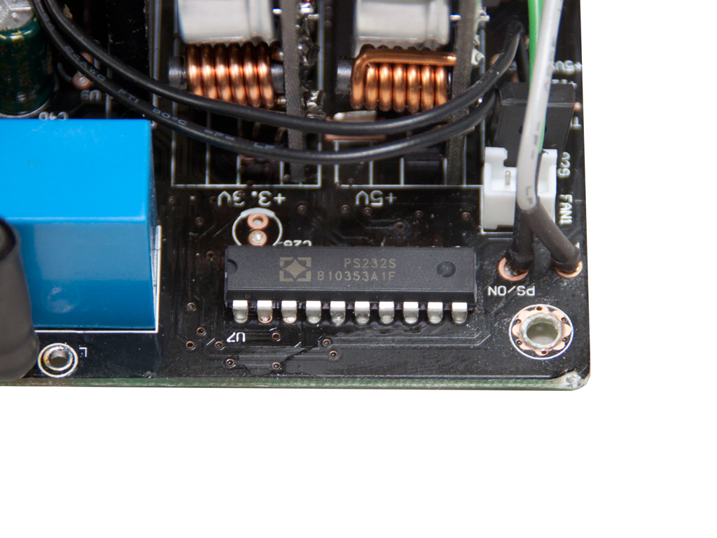
A SITI PS232S supervisor IC is responsible for housekeeping. This IC supports OCP for up to four +12V rails, which matches the virtual rails that this platform has.


We find five polymer caps for some extra ripple filtering on the front of the modular PCB.
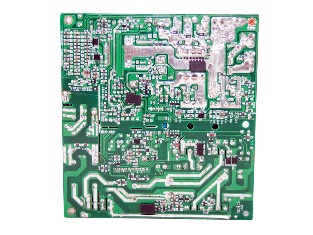
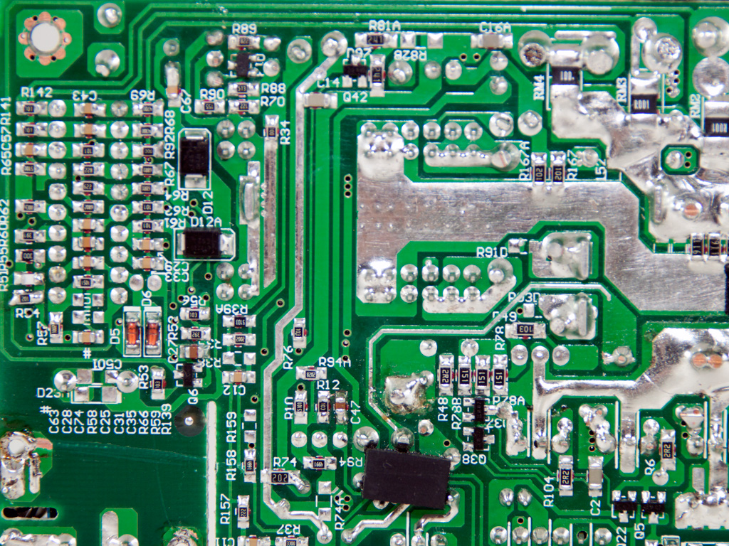
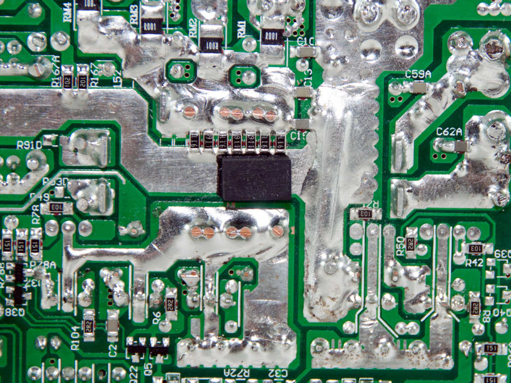


Soldering quality of the main PCB is, that is for sure, below average, and we spotted several blobby solder joints in some areas on the secondary side.
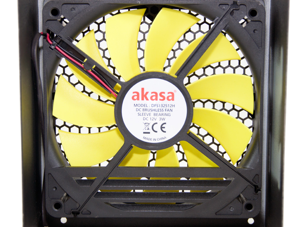
The cooling fan carries Akasa's logo and its model number is DFS132512H (12V, 0.25A, 1700RPM, 91.16CFM, 36.28dBA). It is provided by Young Lin Tech, and exactly the same one is used in the smaller Venom 550 W. It is, in general, silent enough; that is, under normal conditions and to our ears. As you can see from the photo above, this fan utilizes a special frame instead of a plastic shroud to enhance airflow.
Apr 18th, 2024 08:09 EDT
change timezone
Latest GPU Drivers
New Forum Posts
- Will a RTX 4070 TI super bottleneck a Ryzen 9 7950X3D? (32)
- Unlocked Realtek HD Audio Drivers for Windows 11 (Dolby Digital Live/DTS Interactive) (152)
- The TPU UK Clubhouse (24726)
- What are you playing? (20453)
- Gigabyte gpu model differences? (33)
- DDR5 RAM Speeds and the future (25)
- [Official] Meta Quest 3 (43)
- Which air cooler for a ryzen 9 5900x (156)
- Realtek Modded Audio Driver for Windows 10/11 - Only for HDAUDIO (5677)
- Your PC ATM (34484)
Popular Reviews
- Horizon Forbidden West Performance Benchmark Review - 30 GPUs Tested
- PowerColor Radeon RX 7900 GRE Hellhound Review
- Fractal Design Terra Review
- Corsair 2000D Airflow Review
- Minisforum EliteMini UM780 XTX (AMD Ryzen 7 7840HS) Review
- Creative Pebble X Plus Review
- FiiO KB3 HiFi Mechanical Keyboard Review - Integrated DAC/Amp!
- ASUS GeForce RTX 4090 STRIX OC Review
- NVIDIA GeForce RTX 4090 Founders Edition Review - Impressive Performance
- ASUS GeForce RTX 4090 Matrix Platinum Review - The RTX 4090 Ti
Controversial News Posts
- Sony PlayStation 5 Pro Specifications Confirmed, Console Arrives Before Holidays (106)
- NVIDIA Points Intel Raptor Lake CPU Users to Get Help from Intel Amid System Instability Issues (102)
- US Government Wants Nuclear Plants to Offload AI Data Center Expansion (98)
- Windows 10 Security Updates to Cost $61 After 2025, $427 by 2028 (82)
- Developers of Outpost Infinity Siege Recommend Underclocking i9-13900K and i9-14900K for Stability on Machines with RTX 4090 (82)
- TechPowerUp Hiring: Reviewers Wanted for Motherboards, Laptops, Gaming Handhelds and Prebuilt Desktops (71)
- Intel Realizes the Only Way to Save x86 is to Democratize it, Reopens x86 IP Licensing (70)
- AMD Zen 5 Execution Engine Leaked, Features True 512-bit FPU (63)