 27
27
Biostar TZ68A+ LGA1155 Review
The Board - A Closer Look »The Board - Layout


The Biostar TZ68A+ features a red/black/white color scheme, with silvered heatsinks. The first thing worth noting is that this board is not the standard ATX width, stopping short by about an inch or so, which may cause installation issues in some casings. That said though, even with less board area to fit everything into, the layout is very clean, and uncluttered. The back of the board is equally nice, with several long strips of solder on the back to help aid cooling, as we have seen on many many products in the past, but not so commonly today.


The socket area is quite cramped, with capacitors and chokes from the VRM very close by. Flipping the board over we can see several of those "cooling strips" mentioned earlier, as well as quite a few protruding pins, however, our usual test mounts of Corsair and Noctua backplates met with no problems. We can also see that there are many component spots that are unfilled in the back of the socket, and while this might be of some concern, it is perfectly normal for this level of product, and doesn't detract from any function of the board itself. The front of the socket, on the other hand, is completely filled, and not a single open space can be found.


The bottom half of the motherboard is filled with just six expansion slots; two PCIe 2.0 x16 slots (electrically one x16 slot, and one x4 slot), two PCI slots, and one PCIe 2.0 x1 slot. The Biostar TZ68A+ features four DIMM slots for up to 32 GB of memory (4x 8 GB), with a single phase power delivery system for the DIMMs. We were quite eager to see how much of a role this may play when clocking RAM to the limit, as the component choice here differs a fair amount from what we've seen on other products.


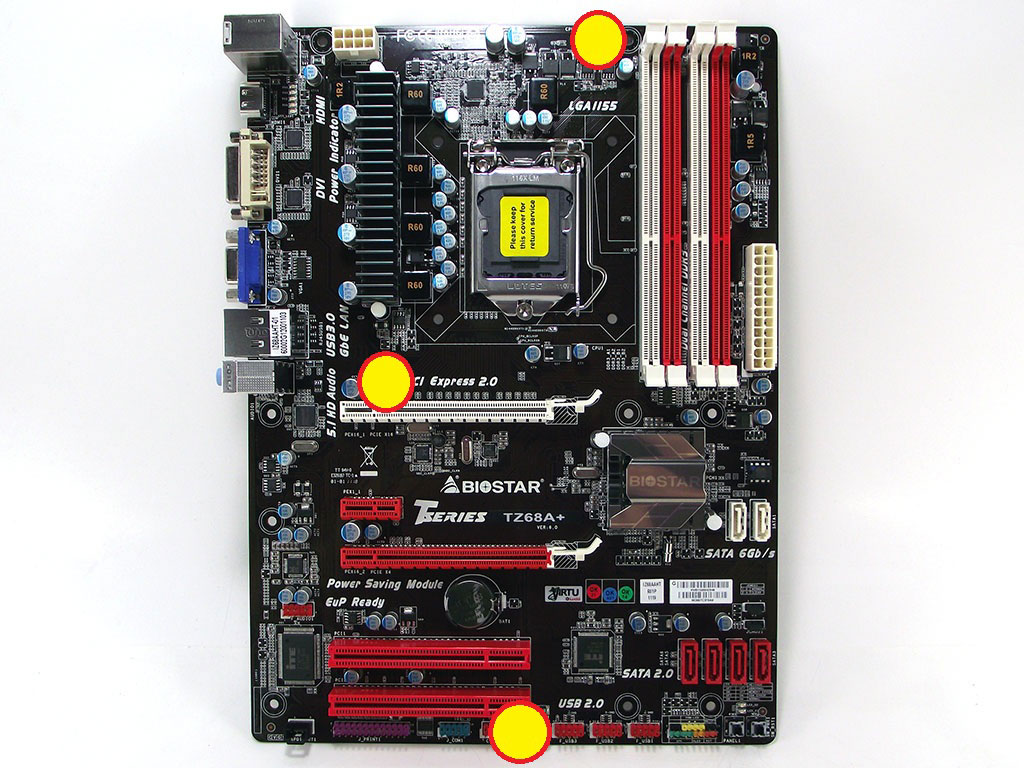
The board's bottom edge carries a full complement of pin headers for just about everything; from a parallel printer port header, to front panel USB 2.0. We have to assume that this board was partially intended for HTPC use or as a replacement in a legacy system, as very few devices today need a printer port. Moving over to the south bridge side of the board, we find several USB headers, a couple of switches, and the front panel connector on the far right edge, to round things out. We also find a serial COM port as well as a fan header on the rear-facing portion, another legacy connector seldom used, but still needed by many users. There are a total of three fan headers on the TZ68A+, two of which are your standard 3-pin, and the third, the CPU_FAN header, is PWM controlled.

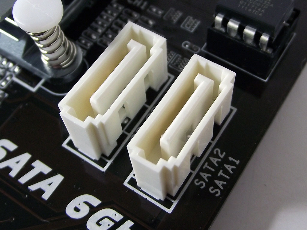

On the back plate we find the least populated I/O area we have ever seen. There are two USB 2.0 and two USB 3.0 ports, a LAN port, a keyboard-only PS/2 connector, and three video outputs; one HDMI, one DVI, and a legacy 15-pin VGA port. For drive connectivity, we find the standard six ports run off of the Intel Z68 chipset, with the two SATA 6 Gb/s ports in white, and the four SATA 3 Gb/s ports in red. Both sets of ports are located so as to not interfere with large dual-slot expansion cards installed into the PCIe x16 slots, too.
Apr 25th, 2024 16:16 EDT
change timezone
Latest GPU Drivers
New Forum Posts
- im new to throttelstop and i think i messed it up by copying others any hints would be very much aprreciated (2)
- What software are you using to monitor CPU temps during gaming session? (13)
- Alphacool CORE 1 CPU block - bulging with danger of splitting? (15)
- What are you playing? (20528)
- What phone you use as your daily driver? And, a discussion of them. (1480)
- Black screen after muting (4)
- Micron f-die overclock issues (0)
- Will a RTX 4070 TI super bottleneck a Ryzen 9 7950X3D? (59)
- How to check flatness of CPUs and coolers - INK and OPTICAL INTERFERENCE methods (111)
- Ghetto Mods (4321)
Popular Reviews
- Fractal Design Terra Review
- Thermalright Phantom Spirit 120 EVO Review
- Corsair 2000D Airflow Review
- Minisforum EliteMini UM780 XTX (AMD Ryzen 7 7840HS) Review
- ASUS GeForce RTX 4090 STRIX OC Review
- NVIDIA GeForce RTX 4090 Founders Edition Review - Impressive Performance
- ASUS GeForce RTX 4090 Matrix Platinum Review - The RTX 4090 Ti
- MSI GeForce RTX 4090 Suprim X Review
- MSI GeForce RTX 4090 Gaming X Trio Review
- Gigabyte GeForce RTX 4090 Gaming OC Review
Controversial News Posts
- Sony PlayStation 5 Pro Specifications Confirmed, Console Arrives Before Holidays (116)
- NVIDIA Points Intel Raptor Lake CPU Users to Get Help from Intel Amid System Instability Issues (106)
- Windows 11 Now Officially Adware as Microsoft Embeds Ads in the Start Menu (104)
- AMD "Strix Halo" Zen 5 Mobile Processor Pictured: Chiplet-based, Uses 256-bit LPDDR5X (101)
- US Government Wants Nuclear Plants to Offload AI Data Center Expansion (98)
- AMD's RDNA 4 GPUs Could Stick with 18 Gbps GDDR6 Memory (86)
- Developers of Outpost Infinity Siege Recommend Underclocking i9-13900K and i9-14900K for Stability on Machines with RTX 4090 (85)
- Windows 10 Security Updates to Cost $61 After 2025, $427 by 2028 (84)