 3
3
Corsair RM Series 650 W Review
Ripple Measurements »Advanced Transient Response Tests
In these tests, we monitor the response of the PSU in two different scenarios. First, a transient load (10 A at +12V, 5 A at 5V, 5 A at 3.3V, and 0.5 A at 5VSB) is applied to the PSU for 200 ms while the latter is working at 20% load. In the second test, the PSU, while working at 50% load, is hit by the same transient load. In both tests, we measure the voltage drops the transient load causes using our oscilloscope. The voltages should remain within the regulation limits defined by the ATX specification. We must stress here that the above tests are crucial since they simulate transient loads a PSU is very likely to handle (e.g., booting a RAID array, an instant 100% load of CPU/VGAs, etc.). We call these tests "Advanced Transient Response Tests", and they are designed to be very tough to master, especially for PSUs with capacities below 500 W.| Advanced Transient Response 20% | ||||
|---|---|---|---|---|
| Voltage | Before | After | Change | Pass/Fail |
| 12 V | 12.125V | 12.019V | 0.87% | Pass |
| 5 V | 5.012V | 4.907V | 2.09% | Pass |
| 3.3 V | 3.283V | 3.159V | 3.78% | Pass |
| 5VSB | 4.995V | 4.948V | 0.94% | Pass |
| Advanced Transient Response 50% | ||||
|---|---|---|---|---|
| Voltage | Before | After | Change | Pass/Fail |
| 12 V | 12.082V | 11.962V | 0.99% | Pass |
| 5 V | 4.969V | 4.860V | 2.19% | Pass |
| 3.3 V | 3.263V | 3.139V | 3.80% | Fail |
| 5VSB | 4.952V | 4.902V | 1.01% | Pass |
Registered deviations on all rails weren't large, but the low nominal voltage of the 3.3V rail led to a fail during the second test. If CWT had increased the voltage on the above rail a little bit, it could easily pass this test, but they unfortunately didn't do so. Skipping to the +12V rail, which is of much higher importance, the deviations were within 1% in both scenarios, so performance was good enough. We would, however, like to see close to 0.5% deviation in both tests.
Below, you will find the oscilloscope screenshots we took during Advanced Transient Response Testing.
Transient Response at 20% Load


Transient Response at 50% Load
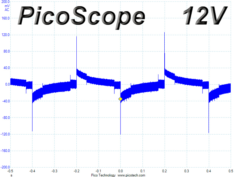


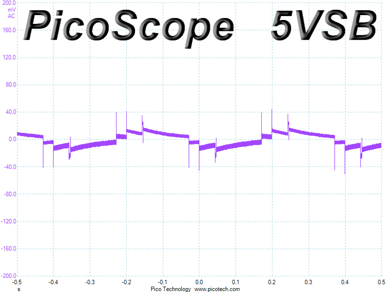
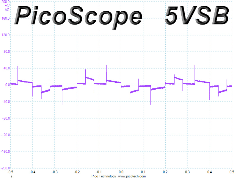
Turn-On Transient Tests
We measure the response of the PSU in simpler scenarios of transient load—during the power-on phase of the PSU—in the next set of tests. In the first test, we turn the PSU off, dial the maximum current the 5VSB can output, and then switch on the PSU. In the second test, we dial the maximum load +12V can handle and start the PSU while the PSU is in standby mode. In the last test, while the PSU is completely switched off (we cut off power or switch off the PSU's on/off switch), we dial the maximum load the +12V rail can handle before switching the PSU on from the loader and restoring power. The ATX specification states that recorded spikes on all rails should not exceed 10% of their nominal values (e.g., +10% for 12V is 13.2V and 5.5V for 5V).

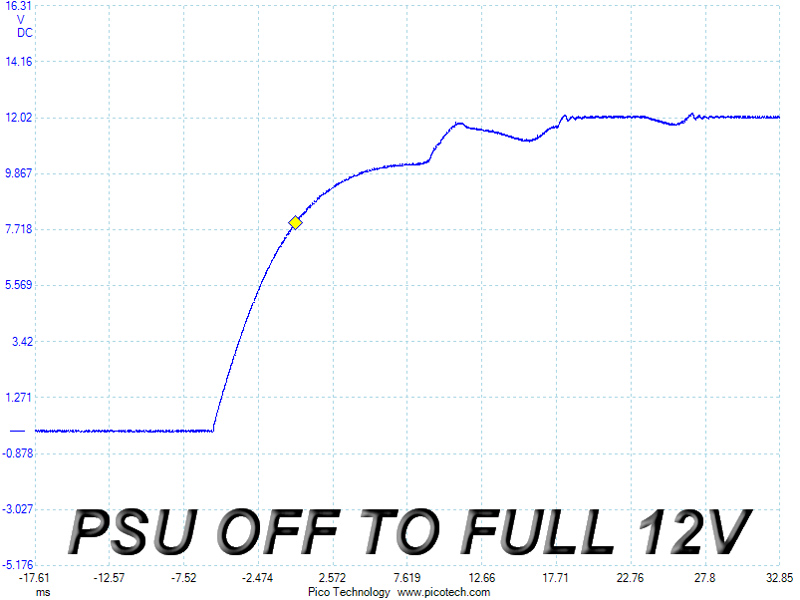
We noticed a really tiny spike on the 5VSB rail, but its slope was almost perfectly smooth in the second test. However, its good performance failed to continue in the third test, where the slope made several bumps before it settled down.
Apr 25th, 2024 09:58 EDT
change timezone
Latest GPU Drivers
New Forum Posts
- Alphacool CORE 1 CPU block - bulging with danger of splitting? (7)
- Ghost of Tsushima PC Port !!!! (14)
- Last game you purchased? (256)
- Meta Horizon OS (17)
- How to check flatness of CPUs and coolers - INK and OPTICAL INTERFERENCE methods (109)
- i7-12800HX Overheating Issues (3)
- (Anti) SFF fun house (355)
- How to quickly & easily fix coil-whine(coil choke noise) (859)
- Asrock A770 Firmware (1)
- RTX 4070 vs RTX 4070 Ti power scaling (5)
Popular Reviews
- Fractal Design Terra Review
- Thermalright Phantom Spirit 120 EVO Review
- Corsair 2000D Airflow Review
- Minisforum EliteMini UM780 XTX (AMD Ryzen 7 7840HS) Review
- ASUS GeForce RTX 4090 STRIX OC Review
- NVIDIA GeForce RTX 4090 Founders Edition Review - Impressive Performance
- ASUS GeForce RTX 4090 Matrix Platinum Review - The RTX 4090 Ti
- MSI GeForce RTX 4090 Suprim X Review
- MSI GeForce RTX 4090 Gaming X Trio Review
- Gigabyte GeForce RTX 4090 Gaming OC Review
Controversial News Posts
- Sony PlayStation 5 Pro Specifications Confirmed, Console Arrives Before Holidays (116)
- NVIDIA Points Intel Raptor Lake CPU Users to Get Help from Intel Amid System Instability Issues (106)
- AMD "Strix Halo" Zen 5 Mobile Processor Pictured: Chiplet-based, Uses 256-bit LPDDR5X (101)
- US Government Wants Nuclear Plants to Offload AI Data Center Expansion (98)
- Windows 11 Now Officially Adware as Microsoft Embeds Ads in the Start Menu (88)
- Developers of Outpost Infinity Siege Recommend Underclocking i9-13900K and i9-14900K for Stability on Machines with RTX 4090 (85)
- Windows 10 Security Updates to Cost $61 After 2025, $427 by 2028 (84)
- AMD's RDNA 4 GPUs Could Stick with 18 Gbps GDDR6 Memory (82)