 2
2
Enermax Platimax 850 W Review
Voltage Regulation & Efficiency »A Look Inside
Before reading this page we strongly suggest to take a look at this article, which will help you understand the internal components of a PSU much better.

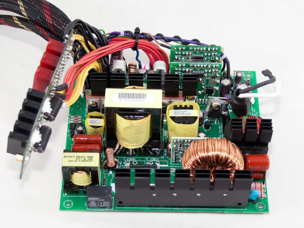
Once we removed the casing we saw a familiar design identical to Enermax Gold platforms, used in Modu 87+ series. Apparently Enermax tuned their Gold design to provide Platinum efficiency and used it for the low capacity Platimax units, while they utilized the newer platform (initially used in Maxrevo PSUs), for Platimax 1050W and 1200W. This is why the two stronger Platimax units are fully modular while all other smaller ones use a semi-modular cabling design. The platform utilized in Platimax 850W uses a resonant converter to boost efficiency along with a synchronous design in the secondary side.
The AC receptacle is attached to a small PCB which holds many components of the transient filtering stage including two CM chokes, two X caps and four Y ones. On the main PCB we find one more CM choke along with an MOV.

The bridge rectifier is bolted on a dedicated heatsink and its model number is LL25XB60. It can handle up to 25A meaning 5750W with 230VAC or 2875W with 115VAC power input. After the bridge we find not the usual one but two capacitors which filter the high frequency ripple of the fully-rectified signal. In front of the caps there are two current sense resistors and a large Y cap.

The APFC uses three Toshiba TK20J60U mosfets, to chop the rectified signal into constant pulse sequences. The boost diode is the classic CREE C3D10060. Right next to the boost diode a thermistor is soldered, responsible for inrush current protection. Near it we find an electromagnetic relay which isolates the thermistor when it finishes its job, after the start up of the PSU. By isolating the thermistor, right after the PSU starts, some efficiency is gained and we allow it to cool down very fast, so its resistance goes up to normal levels and it is ready again to effectively decrease large inrush currents that could possible harm the PSU.
After the resonant tank we find two X caps.


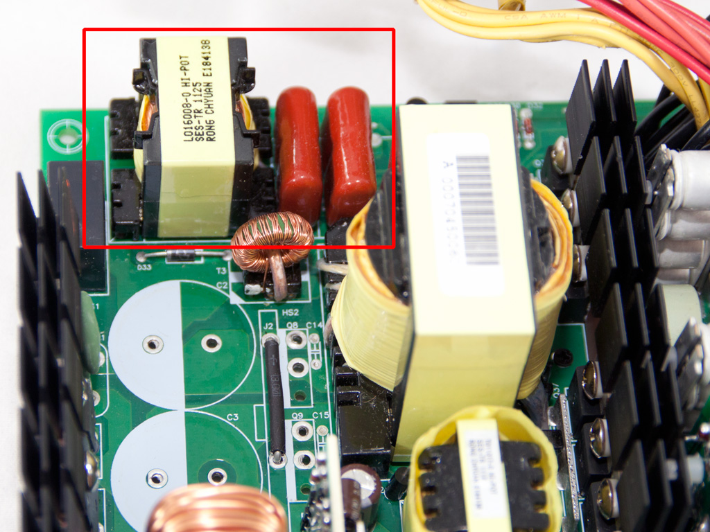
In the secondary side synchronous design is used of course in order to achieve Platinum efficiency. The +12V rails are regulated by six IPP015N04N mosfets while the minor rails are generated by two DC-DC converters. In each VRM there are three APM2556 mosfets. In the secondary side mostly polymer caps are used along with some electrolytic caps and all are provided by Nippon Chemi-Con. To save space Enermax soldered most of the polymer and electrolytic caps on small vertical daughter-boards.

The protections IC is a PS232S, which is soldered on a daughter-board in the secondary side. This IC supports OCP for up to four +12V rails, so it covers the specifications of the EPM850EWT.
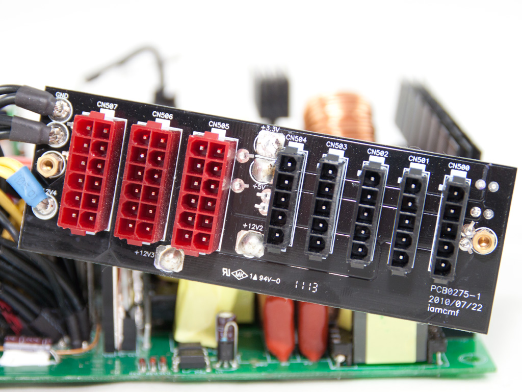

The modular PCB has two electrolytic caps installed on its solder side for further ripple filtering. As you can see soldering quality is not so good here.


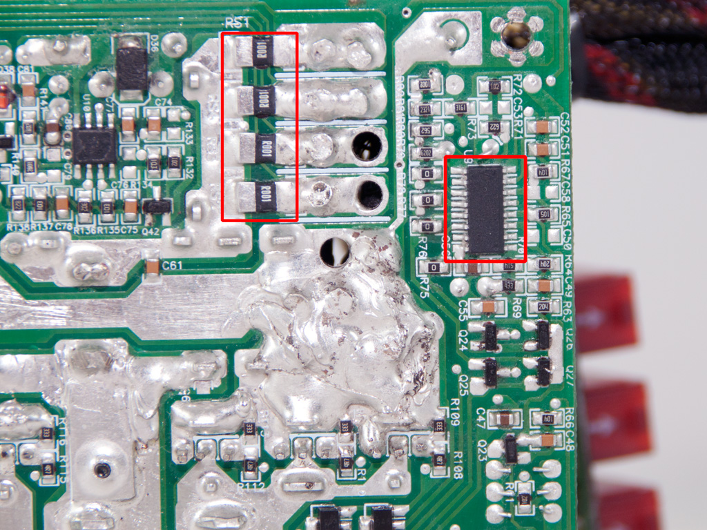
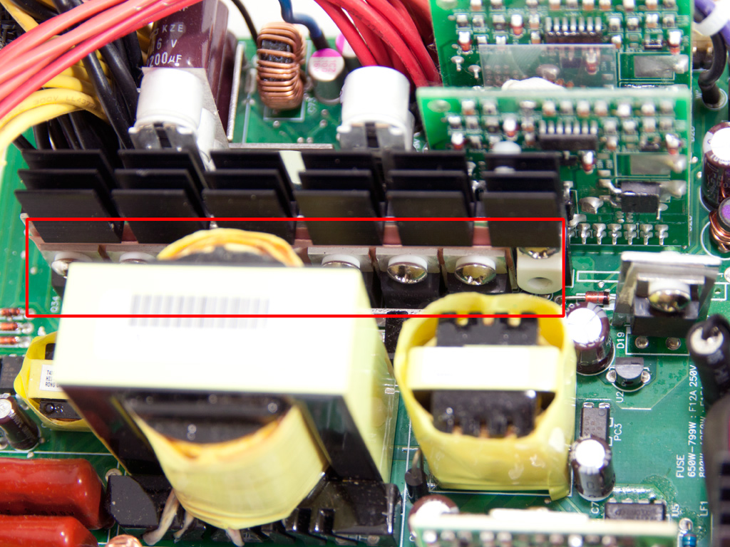
Soldering quality on the main PCB is fairly good in some areas while in others it is mediocre, with sloppy hand made solder joints. On the solder side of the main PCB we also found the resonant controller, probably a CM6901 (the markings on the IC were completely erased). Also the four shunt resistors in the +12V area are a clear indication (along with the PS232S IC) that the unit indeed has four +12V virtual rails.

The cooling fan has Enermax's brand on it and its model number is EA142512M-0A (12V, 0.45A). The twister bearing it is equipped with, ensures good performance and long lifespan along with low noise output. More about twister bearing technology you can find here.
Apr 23rd, 2024 17:29 EDT
change timezone
Latest GPU Drivers
New Forum Posts
- What's your latest tech purchase? (20301)
- ThrottleStop 9.6 Voltage won't change (1)
- need help with motherboard/ ram compability certainty (9)
- FINAL FANTASY XIV: Dawntrail Official Benchmark (71)
- CPB Enabled Boot Loop (8)
- No POST, and no display (8)
- Aida64 cache mem OC (5)
- hacked (72)
- Meta Horizon OS (6)
- windows 11 (4)
Popular Reviews
- Horizon Forbidden West Performance Benchmark Review - 30 GPUs Tested
- Fractal Design Terra Review
- Corsair 2000D Airflow Review
- Thermalright Phantom Spirit 120 EVO Review
- Minisforum EliteMini UM780 XTX (AMD Ryzen 7 7840HS) Review
- ASUS GeForce RTX 4090 STRIX OC Review
- NVIDIA GeForce RTX 4090 Founders Edition Review - Impressive Performance
- ASUS GeForce RTX 4090 Matrix Platinum Review - The RTX 4090 Ti
- Creative Pebble X Plus Review
- MSI GeForce RTX 4090 Gaming X Trio Review
Controversial News Posts
- Sony PlayStation 5 Pro Specifications Confirmed, Console Arrives Before Holidays (116)
- NVIDIA Points Intel Raptor Lake CPU Users to Get Help from Intel Amid System Instability Issues (106)
- AMD "Strix Halo" Zen 5 Mobile Processor Pictured: Chiplet-based, Uses 256-bit LPDDR5X (101)
- US Government Wants Nuclear Plants to Offload AI Data Center Expansion (98)
- Windows 10 Security Updates to Cost $61 After 2025, $427 by 2028 (84)
- Developers of Outpost Infinity Siege Recommend Underclocking i9-13900K and i9-14900K for Stability on Machines with RTX 4090 (84)
- TechPowerUp Hiring: Reviewers Wanted for Motherboards, Laptops, Gaming Handhelds and Prebuilt Desktops (74)
- Intel Realizes the Only Way to Save x86 is to Democratize it, Reopens x86 IP Licensing (70)