 0
0
FSP Aurum CM Gold 750 W Review
Voltage Regulation & Efficiency »A Look Inside
Before reading this page we strongly suggest to take a look at this article, which will help you understand the internal components of a PSU much better.

The main PCB is quite small, underpopulated and the primary and secondary heatsinks are too small, so we don't expect a significant delta difference between the input and output temperatures in the voltage regulation and efficiency measurements. FSP also uses two proprietary ICs, made by themselves, to control the primary and secondary side respectively. We will refer to them below.
The transient filter starts at the AC receptacle with two Y caps and the power wires are wrapped around a ferrite core. It continues on the main PCB with three coils, two X and two Y caps. We didn't find an MOV, something that FSP tends to make a tradition in their platforms. However in this case FSP claims that the MIA IC that this platform uses offers over voltage protection and it can absorb excess surges coming from the power grid. Still we would be more assured if we saw a MOV in the transient filter, since its cost is insignificant.


The single bridge rectifier is bolted on a heatsink. After it we meet the large APFC choke and the primary heatsink which holds the APFC mosfets, two IPB60R165CP, and the boost diode. Right behind the boost diode, attached also on the primary heatsink, there is the 5VSB regulation mosfet, a GE03N70T. We found it strange that FSP claims 3.5A max at 5VSB since this FET supports only up to 3.3A continuous drain current at 25°C and only 2.1A at 100°C.
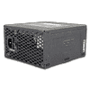
The smoothing/reservoir capacitor is provided by Rubycon (390μF, 450V, 105°C, MXG series). The topology that FSP uses in Aurum is called Active Clamp Reset Forward (ACRF). It offers high efficiency and good power handling capability but up to a certain power level it cannot really compete with other topologies, like double forward, full phase shift etc. In ACRF two mosfets are used, ones plays the role of the main switcher (Q1) and the other is the reset switch (Q2), which disconnects the main capacitor while Q1 is active. Also while Q2 is open, power is transferred from the primary to the secondary side. The main advantage of ACRF is the almost lossless switch of Q1, because while it is turned off the drain voltage is very low. In AU-750M in the role of Q1 is a SPA17N80C3 and as Q2 we find a FQPF3N80C. The APFC/PWM controller is a FSP 6600 IC, for which we didn't find any documentation on the net.


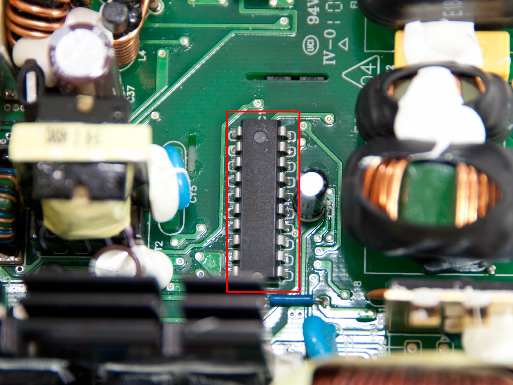
In the secondary side synchronous design is used so the generation of +12V handle mosfets (two IRLB3036). The minor rails are generated from +12V with the help of a DC-DC converter. The mosfets responsible for the regulation of the minor rails reside on the solder side of the main PCB and consist of two pairs of IPD031N03L and IPD050N03L. The PWM controller for the DC-DC converter is the proprietary FSP 6601 IC and all filtering caps of the secondary side, on the main PCB, are provided by Nippon Chemi-Con and rated at 105°C.

We would like to see some heatshrink around these wires.


On the solder side of the modular PCB there are two CapXon caps for current filtering. A wise move from FSP, although we would prefer to see two Japan made caps here.


Soldering quality in general is good enough and we were very pleased with the fact that we didn't find any long component leads. On the secondary side we spotted four current shunts under the +12V wires area, so it seems the PSU indeed has four +12V rails.

The cooling fan is provided by Protechnic Electric and its model number is MGA12012HF-A25 (12V, 0.45A, 2400 RPM, 84.8 CFM, 37 dBA, 155g).
Apr 24th, 2024 20:47 EDT
change timezone
Latest GPU Drivers
New Forum Posts
- The TPU UK Clubhouse (24783)
- (Anti) SFF fun house (346)
- Cinebench crashed my PC. My Wi-Fi stopped working, and I keep getting a "Please wait" screen when I boot up my PC. (28)
- Sharing experience with MSI RTX 3070 vBIOS update to enable Resizable Bar with MB Z490 (2)
- Share your AIDA 64 cache and memory benchmark here (2915)
- Will a RTX 4070 TI super bottleneck a Ryzen 9 7950X3D? (58)
- The best *budget* ATX PC case on the market? (24)
- GTX 1070 Ti - TDP Issues - Always Power Throttling (4)
- 2022-X58/1366 PIN Motherboards NVME M.2 SSD BIOS MOD Collection (656)
- Meta Horizon OS (15)
Popular Reviews
- Fractal Design Terra Review
- Thermalright Phantom Spirit 120 EVO Review
- Corsair 2000D Airflow Review
- Minisforum EliteMini UM780 XTX (AMD Ryzen 7 7840HS) Review
- ASUS GeForce RTX 4090 STRIX OC Review
- NVIDIA GeForce RTX 4090 Founders Edition Review - Impressive Performance
- ASUS GeForce RTX 4090 Matrix Platinum Review - The RTX 4090 Ti
- MSI GeForce RTX 4090 Suprim X Review
- MSI GeForce RTX 4090 Gaming X Trio Review
- Gigabyte GeForce RTX 4090 Gaming OC Review
Controversial News Posts
- Sony PlayStation 5 Pro Specifications Confirmed, Console Arrives Before Holidays (116)
- NVIDIA Points Intel Raptor Lake CPU Users to Get Help from Intel Amid System Instability Issues (106)
- AMD "Strix Halo" Zen 5 Mobile Processor Pictured: Chiplet-based, Uses 256-bit LPDDR5X (101)
- US Government Wants Nuclear Plants to Offload AI Data Center Expansion (98)
- Windows 10 Security Updates to Cost $61 After 2025, $427 by 2028 (84)
- Developers of Outpost Infinity Siege Recommend Underclocking i9-13900K and i9-14900K for Stability on Machines with RTX 4090 (84)
- TechPowerUp Hiring: Reviewers Wanted for Motherboards, Laptops, Gaming Handhelds and Prebuilt Desktops (78)
- AMD's RDNA 4 GPUs Could Stick with 18 Gbps GDDR6 Memory (71)