 0
0
LEPA G850-MAS 850 W Review
Voltage Regulation & Efficiency »A Look Inside
Before reading this page, we strongly suggest a look at this article, which will help you understand the internal components of a PSU better.


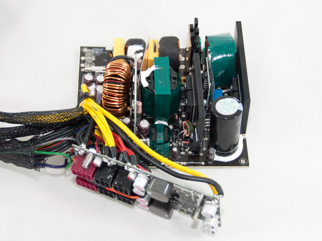

Contrary to most of the LEPA G series units, this one is made by Channel Well Technology (CWT) and is, to be more specific, based on CWT's fresh PUQ-G platform. A conventional double forward topology is utilized on the primary side, while a synchronous rectification along with two VRMs for the generation of the minor rails is used on the secondary side. Finally, CWT tried to reduce the production cost by using a single-sided PCB.
We find the first part of the transient filtering stage at the AC receptacle, which, in this case, consists of only a pair of Y caps. The rest of the parts on the main PCB complete the transient filtering stage with two X and two Y caps, two CM chokes, and an MOV.


The two parallel bridge rectifiers are bolted on a dedicated heatsink, and a copper plate is used to cool them down. Their model number is GBU806 and each can handle up to 8 A of current.


In the APFC, two IPW60R190E6 fets are used along with a CREE C3D06060 boost diode. The single hold-up cap (470μF, 400V, 105°C) is provided by Panasonic and is small for the unit's capacity. Finally, the combo PFC/PWM controller is a Champion CM6802 IC, which is an upgraded version of the famous CM6800 offering higher efficiency.

The thermistor, responsible for protection against large inrush currents, is backed up by an electromagnetic relay.


The main switchers are two Infineon IPW60R099C6 fets configured in double forward topology. On the same heatsink, we also found a STF3NK80Z fet that we suspect of being utilized by the 5VSB rectification circuit.

On the secondary side, synchronous rectification is used, and the +12V rail rectify five IPD031N06L3 fets. Like every other PUQ platforms we examined in the past, this one doesn't use a heatsink to cool down the +12V fets. The PCB that houses them handles this job with the help of the PSU's fan and three bus bars on its solder side.


All electrolytic caps on the secondary side are provided by Nippon Chemi-Con and are rated at 105°C. We also found a single polymer cap.

The WT7502 supervisor IC is hidden by a jungle of wires. It only offers basic protections, excluding OCP for the +12V rail, which is fine since OCP in a single +12V rail PSU of such high capacity is useless anyway.


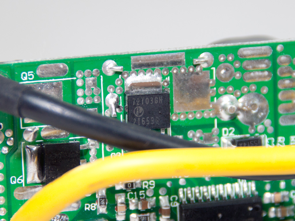
The VRMs that generate the minor rails are installed directly on the modular PCB for lower voltage drops. The common PWM controller for both VRMs is an APW7159 IC, and a pair of AP72T03GH fets is used with each one.


At the front of the modular PCB, we find many polymer filtering caps. The big ones with the pink markings are from Enesol. Unfortunately, we couldn't identify the rest with purple and red markings.


The main PCB features a decent soldering quality, which is, however, still far away from high-end implementations. It won't cause any problems and will allow the PSU to deploy its full performance. We, to our great satisfaction, didn't spot any long component leads.

The cooling fan is provided by Yate Loon Electronics and its model number is D14BH-12 (12V, 0.7 A, 2800 RPM, 140 CFM, 48.5 dBA max). It is quite strong since it has to cool the +12V fets down mostly on its own. It is quiet noisy at increased RPMs.
Apr 24th, 2024 20:31 EDT
change timezone
Latest GPU Drivers
New Forum Posts
- The TPU UK Clubhouse (24783)
- (Anti) SFF fun house (346)
- Cinebench crashed my PC. My Wi-Fi stopped working, and I keep getting a "Please wait" screen when I boot up my PC. (28)
- Sharing experience with MSI RTX 3070 vBIOS update to enable Resizable Bar with MB Z490 (2)
- Share your AIDA 64 cache and memory benchmark here (2915)
- Will a RTX 4070 TI super bottleneck a Ryzen 9 7950X3D? (58)
- The best *budget* ATX PC case on the market? (24)
- GTX 1070 Ti - TDP Issues - Always Power Throttling (4)
- 2022-X58/1366 PIN Motherboards NVME M.2 SSD BIOS MOD Collection (656)
- Meta Horizon OS (15)
Popular Reviews
- Fractal Design Terra Review
- Thermalright Phantom Spirit 120 EVO Review
- Corsair 2000D Airflow Review
- Minisforum EliteMini UM780 XTX (AMD Ryzen 7 7840HS) Review
- ASUS GeForce RTX 4090 STRIX OC Review
- NVIDIA GeForce RTX 4090 Founders Edition Review - Impressive Performance
- ASUS GeForce RTX 4090 Matrix Platinum Review - The RTX 4090 Ti
- MSI GeForce RTX 4090 Suprim X Review
- MSI GeForce RTX 4090 Gaming X Trio Review
- Gigabyte GeForce RTX 4090 Gaming OC Review
Controversial News Posts
- Sony PlayStation 5 Pro Specifications Confirmed, Console Arrives Before Holidays (116)
- NVIDIA Points Intel Raptor Lake CPU Users to Get Help from Intel Amid System Instability Issues (106)
- AMD "Strix Halo" Zen 5 Mobile Processor Pictured: Chiplet-based, Uses 256-bit LPDDR5X (101)
- US Government Wants Nuclear Plants to Offload AI Data Center Expansion (98)
- Windows 10 Security Updates to Cost $61 After 2025, $427 by 2028 (84)
- Developers of Outpost Infinity Siege Recommend Underclocking i9-13900K and i9-14900K for Stability on Machines with RTX 4090 (84)
- TechPowerUp Hiring: Reviewers Wanted for Motherboards, Laptops, Gaming Handhelds and Prebuilt Desktops (78)
- AMD's RDNA 4 GPUs Could Stick with 18 Gbps GDDR6 Memory (71)