 7
7
Silverstone Nightjar 520 W Review
Voltage Regulation, Hold-up Time & Inrush Current »A Look Inside & Component Analysis
Before reading this page, we strongly suggest a look at this article, which will help you understand the internal components of a PSU much better. Our main tool for the disassembly of the PSU is a Thermaltronics TMT-9000S soldering and rework station. It is of extreme quality and is equipped with a matching de-soldering gun. With such equipment in hand, breaking apart every PSU is like a walk in the park!


This unit is made by Seasonic and is identical as we already stated to their SS-520FL offering. The primary side uses a full bridge topology, along with an LLC resonant converter for increased efficiency. The secondary side uses a synchronous scheme with two DC-DC converters for the generation of the minor rails. Both VRMs are directly on the modular PCB to further reduce energy losses due to excessive amounts of wiring.

Although the +12V mosfets have been moved from the main PCB's solder side to a dedicated heatsink, the enclosure plays an active role in cooling them down, and several thermal pads ensure its good contact with the PCB.
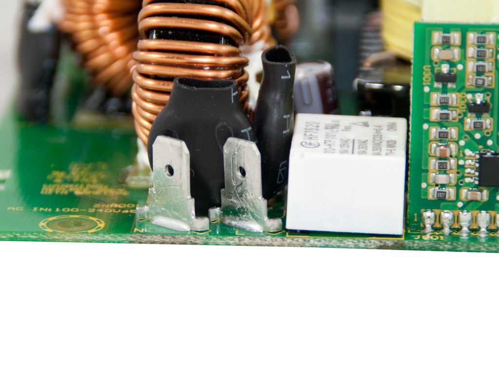
Behind the AC receptacle is a small PCB. It is protected by a metal shield for EMI suppression. Four Y caps, a CM choke, and a single X cap are installed here. All other transient filtering components are on the main PCB. These include two additional CM chokes, two X and Y caps, each, and an MOV. There is also an NTC thermistor. It protects the unit against large inrush currents, and an electromagnetic relay cuts it off the circuit once it finishes its job. Lastly, spade terminals are used on the wires transferring the load, which makes their removal an easy task.

The standby Quasi-Resonant PWM Controller is an ICE2QR4765 IC.


The parallel bridge rectifiers are two GBJ2506. They are too powerful for the needs of this unit and we cannot help but wonder why smaller ones weren't used to cut on cost.
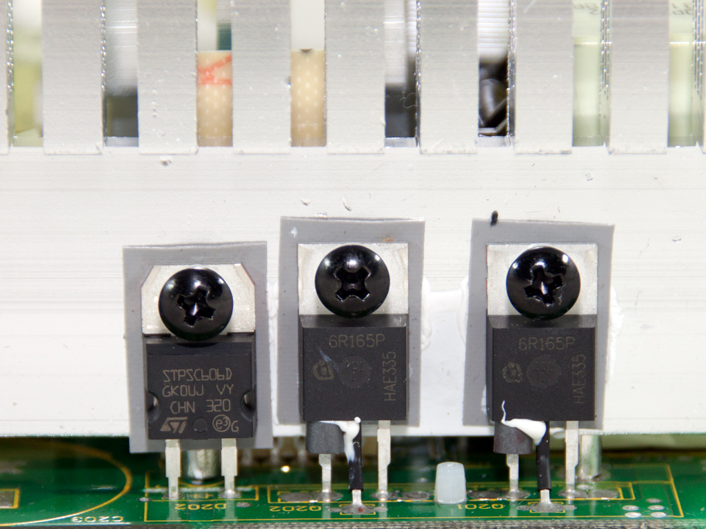


Two Infineon IPP60R165CP fets and an STPSC606 boost diode (the SS-520FL uses a CREE C3D06060) are used in the APFC. The hold-up cap is provided by Hitachi (420V, 330µF) and is rated at 105°C, while the APFC controller, an NPC1654, is hiding on a small daughter-board between the APFC and the primary heatsink.
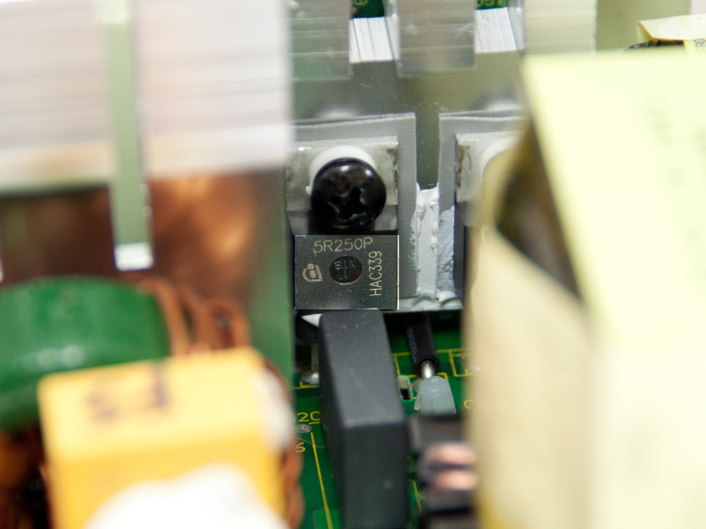
The main switchers, four Infineon IPP50R250CPs, are arranged in a full bridge topology, and an LLC resonant converter is utilized to provide a significant efficiency boost.

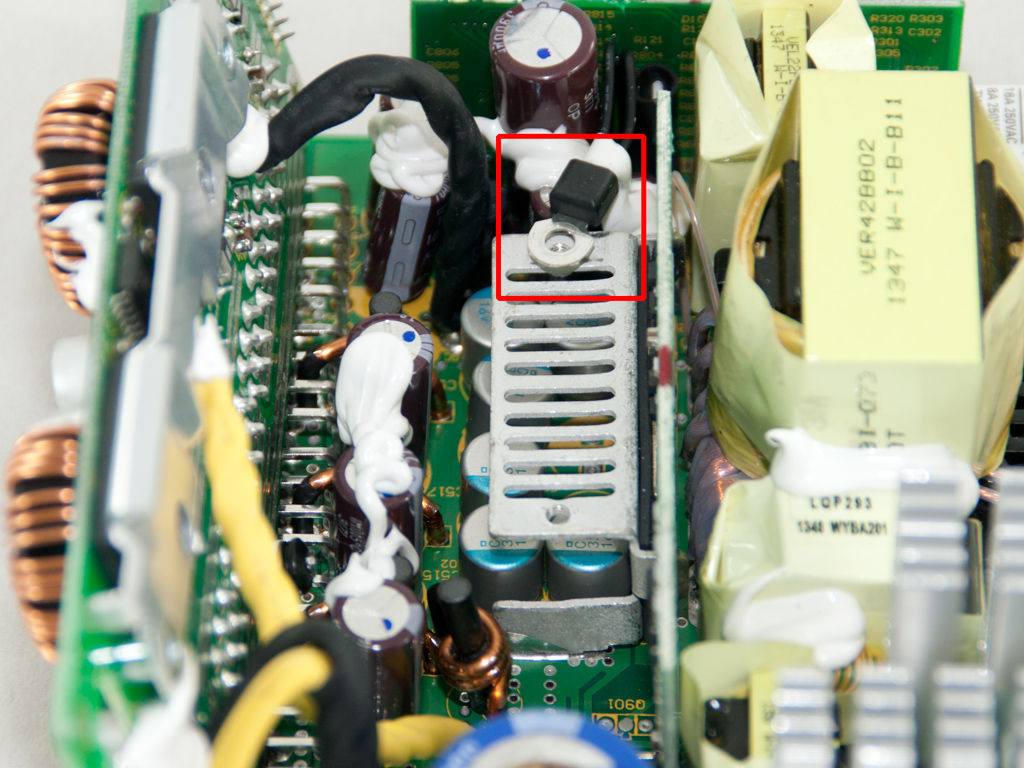


The +12V fets and LLC resonant controller, a Champion CM6901 IC, are installed on a vertical PCB in the secondary side. Two heatsinks cool the aforementioned fets, and a thermistor that has been attached to the top heatsink provides information to the OTP circuit. A series of polymer and several electrolytic caps by Nippon Chemi-Con (105°C, KZE series) filter this rail.


To reduce energy dissipation, both DC-DC converters generating the minor rails are directly on the modular PCB. Their common PWM controller is an APW7159 PWM IC, and each VRMs uses three RJK0332DPB fets. As you can see in the photos above, a heatsink has been attached to the modular panel's rear side. It provides EMI protection and plays a key role in keeping the VRMs cool.


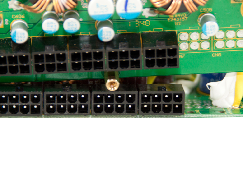
Many polymer caps, with all being provided probably by Nippon Chemi-Con, at the front of the modular board are used for ripple-filtering purposes. Seasonic's unit uses Enesol caps here. The bottom sockets are directly soldered to the main PCB to further reduce energy losses.


The supervisor IC, a Weltrend WT7527, is installed to this PCB, along with an LM339 quad-voltage comparator. The WT7527 supports up to two virtual +12V rails, but this PSU only has one.


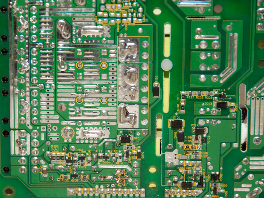
The main PCB's soldering quality is quite good overall, and all component leads were carefully trimmed.
Apr 23rd, 2024 11:26 EDT
change timezone
Latest GPU Drivers
New Forum Posts
- Asus Crosshair X670E - CPU Package temps (10)
- Is there a technical reason that Windows 11 doesn't have built into it battery charge limitation? (29)
- Core PL1 + GPU PL1 + Ring EDP OTHER (4)
- 5.1 or 7.1 software solutions (1)
- FINAL FANTASY XIV: Dawntrail Official Benchmark (64)
- What's your latest tech purchase? (20297)
- SOYO RX580 2048SP Original Bios (8)
- Unlock the shaders - AMD Radeon RX 560D (323)
- Possible near-future 2024 Arrow Lake build.... (49)
- What are you playing? (20521)
Popular Reviews
- Horizon Forbidden West Performance Benchmark Review - 30 GPUs Tested
- Fractal Design Terra Review
- Corsair 2000D Airflow Review
- Thermalright Phantom Spirit 120 EVO Review
- Minisforum EliteMini UM780 XTX (AMD Ryzen 7 7840HS) Review
- ASUS GeForce RTX 4090 STRIX OC Review
- NVIDIA GeForce RTX 4090 Founders Edition Review - Impressive Performance
- ASUS GeForce RTX 4090 Matrix Platinum Review - The RTX 4090 Ti
- Creative Pebble X Plus Review
- MSI GeForce RTX 4090 Gaming X Trio Review
Controversial News Posts
- Sony PlayStation 5 Pro Specifications Confirmed, Console Arrives Before Holidays (116)
- NVIDIA Points Intel Raptor Lake CPU Users to Get Help from Intel Amid System Instability Issues (105)
- AMD "Strix Halo" Zen 5 Mobile Processor Pictured: Chiplet-based, Uses 256-bit LPDDR5X (101)
- US Government Wants Nuclear Plants to Offload AI Data Center Expansion (98)
- Windows 10 Security Updates to Cost $61 After 2025, $427 by 2028 (84)
- Developers of Outpost Infinity Siege Recommend Underclocking i9-13900K and i9-14900K for Stability on Machines with RTX 4090 (82)
- TechPowerUp Hiring: Reviewers Wanted for Motherboards, Laptops, Gaming Handhelds and Prebuilt Desktops (74)
- Intel Realizes the Only Way to Save x86 is to Democratize it, Reopens x86 IP Licensing (70)