 5
5
Thermaltake Toughpower DPS 850 W Review
Voltage Regulation, Hold-up Time & Inrush Current »A Look Inside & Component Analysis
Before reading this page, we strongly suggest a look at this article, which will help you understand the internal components of a PSU much better. Our main tool for the disassembly of the PSU is a Thermaltronics TMT-9000S soldering and rework station. It is of extreme quality and is equipped with a matching de-soldering gun. With such equipment in hand, breaking apart every PSU is like a walk in the park!


We couldn't safely identify the OEM of this unit, but suspect Channel Well Technology, though other reliable sources point towards Sirfa. Thermaltake failed to provide us with any hints. The design is cutting-edge since we came across an LLC resonant converter in the primary side. The +12V fets in the secondary side are directly attached to the main transformer in an effort to decrease energy dissipation, and the DC-DC converters that generate the minor rails are installed on the modular PCB for exactly the same reason. The APFC converter and the main switchers are controlled by analogue circuits, while +12V is digitally controlled. Since we didn't find a PWM controller for the VRMs that generate the minor rails, we are pretty sure that these are digitally controlled as well.
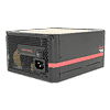
The first part of the transient filter starts at the AC receptacle with two Y caps. The second part is located on the main PCB and consists of two CM chokes, three X caps, two pairs of Y caps—with the second one after the bridge rectifier—and an MOV.
The bridge rectifier is a single U30K80R.


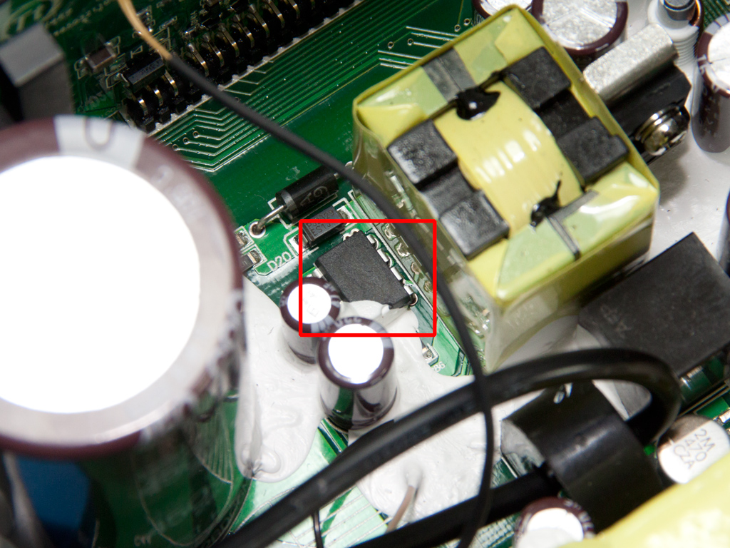
A cable loop between the bridge rectifier and an X cap passes through a CT (Current Transformer) that measures the electric current the PSU draws. It is possible to calculate the true efficiency of the unit with this information in hand. We also spotted an LM2576-ADJ buck regulator near the CT. The buck regulator is most likely exploited by the 5VSB circuit.


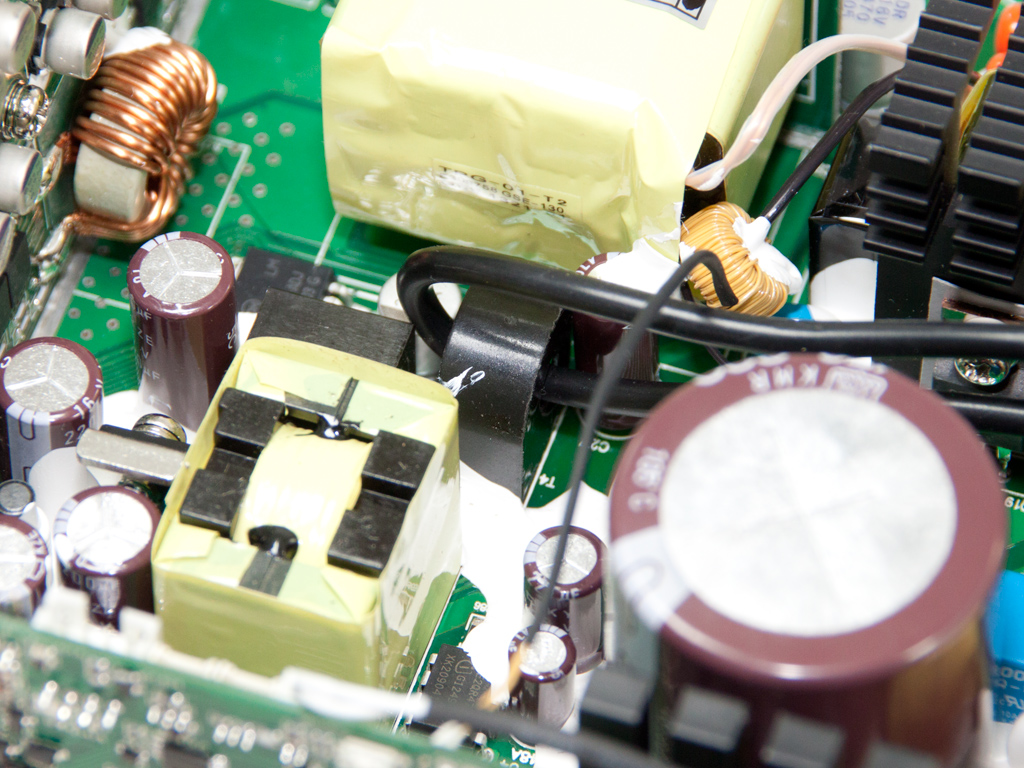
The APFC converter uses two Infineon SPW20N60C3 fets and a single CREE C3D10060A boost diode. The single bulk cap is provided by Nippon Chemi-Con (450 V, 680 μF, 105°C, KMR series). There is a vacant spot for another bulk cap on the main PCB, but it is apparently only occupied in higher capacity models.
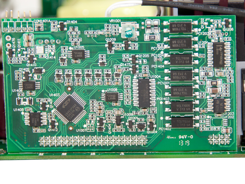


Next to the APFC fets is a pretty large daughter-board that hosts all ICs controlling the PSU. On the right side of this PCB is an LM339 voltage comparator and next to it are seven optocouplers. On the left side are a CM6901 LLC resonant controller and C8051F380, which is a fully integrated Silicon Lab mixed-signal System-on-a-Chip MCU. We find the socket the fan connects to and two cables providing temperature and current information, probably to the MCU handling digital control and protections, on the same PCB.


Two FCP22N60Es function as main switchers. In front of their heatsink are the capacitive and inductive parts of the LLC resonant converter.

A single SBL30L45FCT SBR rectifies the 5VSB rail, while the standby PWM controller is an Infineon ICE2QR4765.


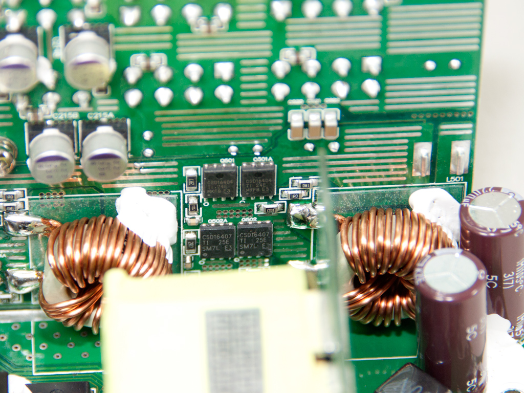
The main transformer is directly attached to a PCB that holds all the fets rectifying the +12V rail. This greatly reduces energy losses which boosts efficiency, especially at higher loads. +12V utilizes six Infineon BSC031N06NS3 fets in total. The secondary rails are generated by two VRMs (Voltage Regulation Modules) installed on the modular PCB. Each VRM uses two CSD16407 and CSD16404 fets, each.


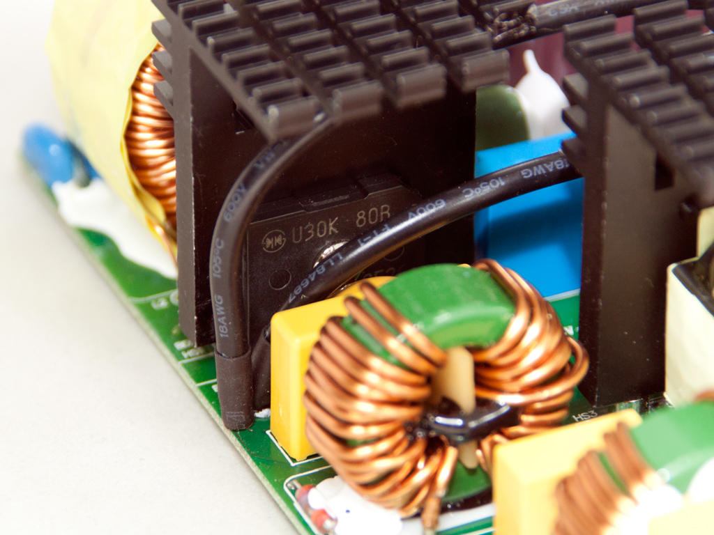
In the secondary side, mostly polymer caps filter the +12V rail. There are also a few electrolytic Chemi-Con ones. We noticed that there are four empty cap spots. The number of polymer caps used is apparently adequate; that is, according to Thermaltake's engineers.
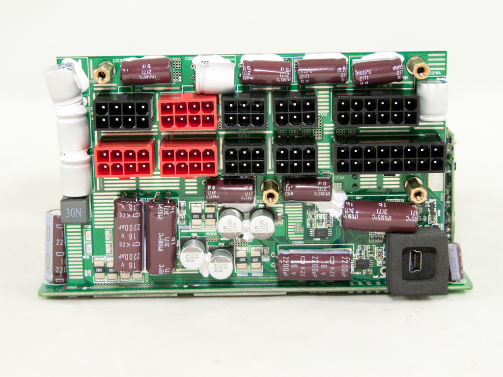


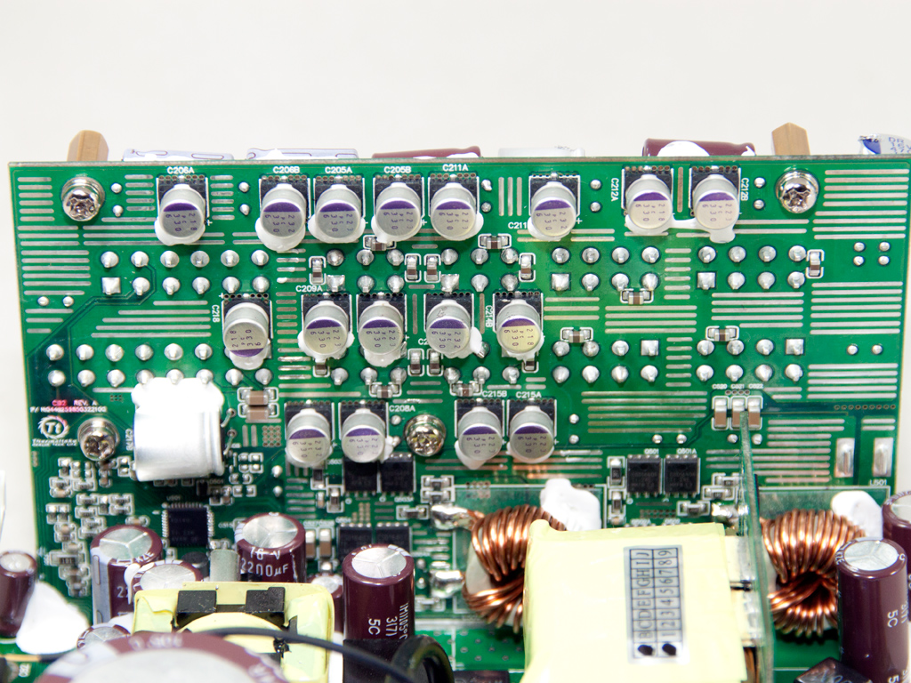
On the front of the modular PCB are many polymer caps and ten electrolytic Chemi-Con ones.


A polymer cap of the modular PCB apparently passed the quality check by unnoticed. It has a hole which looks as though it was caused by a soldering iron; but it was actually caused by one of the top chassis screws, which is why it passed under the radar. This cap is very close to this screw, so the latter inevitably punched a hole into it. Polymer caps thankfually don't use liquid (wet) electrolyte, but the fact that this cap's internals are exposed will affect its reliability, that's for sure.


Soldering quality on the rear side of the main PCB is quite good, and all component leads were carefully trimmed.


The cooling fan is provided by Yate Loon, and its model number is D14BH-12 (12 V, 0.7 A, 140 mm, 2800 RPM, 140 CFM, 48.5 dBA). It uses ball-bearings and is too strong for even a Gold certified, 850 W unit with reduced cooling requirements.
Apr 19th, 2024 09:31 EDT
change timezone
Latest GPU Drivers
New Forum Posts
- What phone you use as your daily driver? And, a discussion of them. (1453)
- Should the CDPR make the Fallout 5 instead? (30)
- Linus watercools (29)
- Gigabyte gpu model differences? (60)
- Do you use Linux? (239)
- [GPU-Z Test Build] Driver unsigned warning on Windows 7/8 (4)
- [GPU-Z Test Build] Resizable BAR shows as "Yes" when Supported but Disabled (26)
- XFX RX560 1024 shaders 16 CU 4GB from Aliexpress (7)
- AMD RX 7000 series GPU Owners' Club (1066)
- 5.1 or 7.1 software solutions (0)
Popular Reviews
- Horizon Forbidden West Performance Benchmark Review - 30 GPUs Tested
- PowerColor Radeon RX 7900 GRE Hellhound Review
- Fractal Design Terra Review
- Corsair 2000D Airflow Review
- Thermalright Phantom Spirit 120 EVO Review
- Minisforum EliteMini UM780 XTX (AMD Ryzen 7 7840HS) Review
- Creative Pebble X Plus Review
- FiiO KB3 HiFi Mechanical Keyboard Review - Integrated DAC/Amp!
- ASUS GeForce RTX 4090 STRIX OC Review
- NVIDIA GeForce RTX 4090 Founders Edition Review - Impressive Performance
Controversial News Posts
- Sony PlayStation 5 Pro Specifications Confirmed, Console Arrives Before Holidays (110)
- NVIDIA Points Intel Raptor Lake CPU Users to Get Help from Intel Amid System Instability Issues (102)
- US Government Wants Nuclear Plants to Offload AI Data Center Expansion (98)
- Windows 10 Security Updates to Cost $61 After 2025, $427 by 2028 (82)
- Developers of Outpost Infinity Siege Recommend Underclocking i9-13900K and i9-14900K for Stability on Machines with RTX 4090 (82)
- TechPowerUp Hiring: Reviewers Wanted for Motherboards, Laptops, Gaming Handhelds and Prebuilt Desktops (71)
- Intel Realizes the Only Way to Save x86 is to Democratize it, Reopens x86 IP Licensing (70)
- AMD Zen 5 Execution Engine Leaked, Features True 512-bit FPU (63)