 0
0
Thortech Thunderbolt Plus 1000 W Review
Voltage Regulation & Efficiency »A Look Inside
Before reading this page we strongly suggest to take a look at this article, which will help you understand the internal components of a PSU much better.


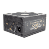
Similar to all Thortech PSUs the OEM of this unit is High Power/Sirfa. Since the dimensions of the enclosure are compact the main PCB is small and densely populated. The design/technology used is not cutting edge, that's for sure. In the primary side we don't meet an LLC resonant converter or any other topology that allows for ZVS (Zero Voltage Switching) switching of the main choppers, something that would significantly boost efficiency. In the secondary side a synchronous design is used along with two DC-DC converters for the generation of the non-primary rails (5V and 3.3V). Besides the standard components in this unit an 8-bit controller is also present and it is actually the brain of the iPower meter device. This controller, along with the rest of the required circuit for the iPower meter, is the main difference among the plain Thunderbolt and the Plus models. Finally, we removed the APFC heatsink along with a CM choke of the transient filter to clear the view to crucial components.
As usual we will start our internals description from the transient filtering stage. This starts right at the AC receptacle with one X and two Y caps. It continues on the main PCB with one X and two Y caps, two CM chokes and an MOV.

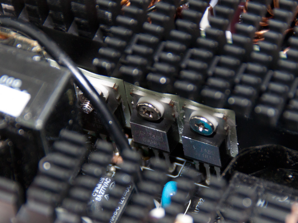
The two parallel bridge rectifiers, contrary to the 1200W model, are not bolted on a heatsink and their model number is GBJ 2506. Here we should note that by leaving them practically on air we increase the unit's efficiency a bit, since in a diode as its operating temperature increases its voltage drop decreases, something that leads of course to lower energy losses.


In the APFC section three SPW24N60C3 are used along with a single boost diode. The two parallel hold up caps are provided by Rubycon (390μF, 400V, 105°C). After the aforementioned caps we meet the two main choppers, two SPW24N60C3 fets.


This red wire, shown on both of the above photos, along with a black one provide the number of Amperes that the unit pulls from the power grid, for the total efficiency percentage to be calculated and shown on the iPower meter's screen.
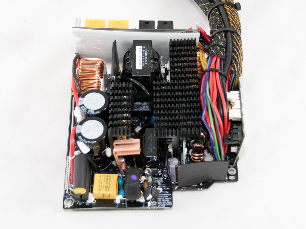
The combo PFC/PWM controller is a Champion CM6800AG, not the most energy efficiency choice for a Gold unit. We usually see this controller in Bronze efficiency units.

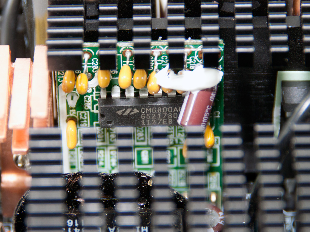
The thermistor, responsible for inrush current protection, is bypassed by an electromagnetic relay once the start up phase of the unit finishes.


In the secondary side synchronous design is used so the +12V rail is regulated by eight AOT480L fets. Exactly the same are used in the 1200W model too, so there is quite some headroom here. The minor rails are generated from +12V through two VRMs (Voltage regulation Modules). Each VRM uses an APW7073 PWM controller and two pair of fets. We were able to recognize one pair (IPD060N03L). All the filtering caps in the secondary side are Japan made (Chemi-Con), rated at 105°C and besides electrolytics some polymers are also used.
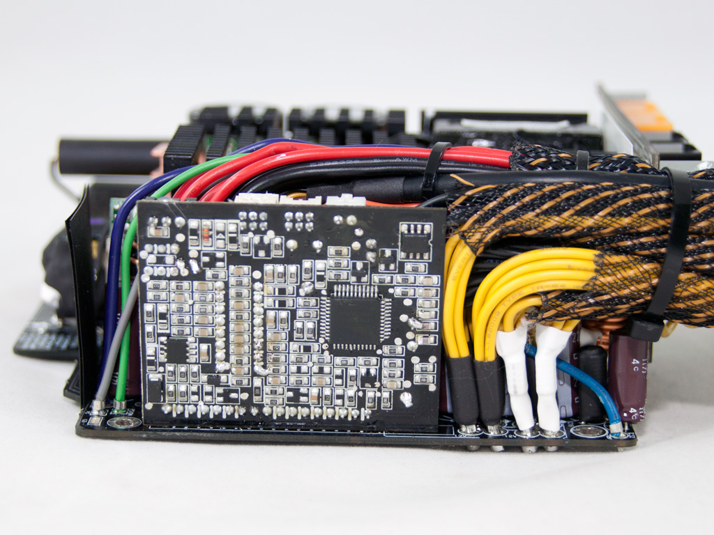

This vertical PCB houses the brain of the iPower meter, an 8-bit micro-controller (EM78M611E). On the other side the supervisor IC, a PS224, is installed. This IC provides OCP for up to two +12V rails and incorporates all protections except OTP.


On the front side of the modular PCB there aren't any extra filtering caps while the solder side is fully covered by a white piece of plastic.

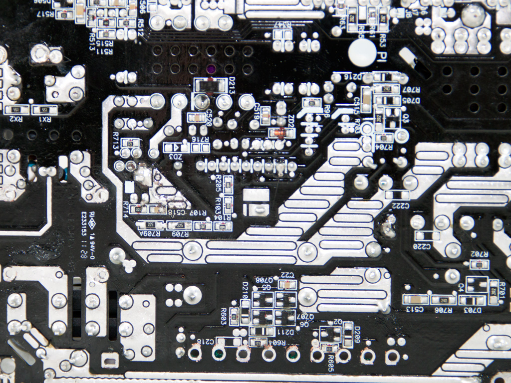


The main PCB enjoys quite good soldering quality and to make things even better we didn't notice any long component leads. In the area where all +12V wires are connected to the PCB there are four shunt resistors, which are usually used to provide current readings to the supervisor IC in order to trigger OCP when needed. In this case we suspect that they are used by the EM78M611E controller for the DC Watts calculation. There are also two shunts near the 5V and 3.3V islands and most likely they are used for the same task.

The cooling fan is provided by Globe Fan and its model number is RL4Z B1352512H-3M (12V, 0.33A). As you can see it has eleven blades and a plastic baffle is used to direct the airflow towards the rear side of the PSU.
Apr 23rd, 2024 23:57 EDT
change timezone
Latest GPU Drivers
New Forum Posts
- Which new games will you be buying? (300)
- Official Board Game Discussion (10)
- need help with motherboard/ ram compability certainty (15)
- Flashing lenovo BIOS (11)
- FINAL FANTASY XIV: Dawntrail Official Benchmark (72)
- What phone you use as your daily driver? And, a discussion of them. (1455)
- I am getting artifacting when I change Windows security settings. Is my GPU failing, or is this just a Windows issue? (9)
- Cinebench crashed my PC. My Wi-Fi stopped working, and I keep getting a "Please wait" screen when I boot up my PC. (26)
- What's your latest tech purchase? (20321)
- CPB Enabled Boot Loop (10)
Popular Reviews
- Fractal Design Terra Review
- Corsair 2000D Airflow Review
- Thermalright Phantom Spirit 120 EVO Review
- Minisforum EliteMini UM780 XTX (AMD Ryzen 7 7840HS) Review
- ASUS GeForce RTX 4090 STRIX OC Review
- NVIDIA GeForce RTX 4090 Founders Edition Review - Impressive Performance
- ASUS GeForce RTX 4090 Matrix Platinum Review - The RTX 4090 Ti
- MSI GeForce RTX 4090 Suprim X Review
- MSI GeForce RTX 4090 Gaming X Trio Review
- Gigabyte GeForce RTX 4090 Gaming OC Review
Controversial News Posts
- Sony PlayStation 5 Pro Specifications Confirmed, Console Arrives Before Holidays (116)
- NVIDIA Points Intel Raptor Lake CPU Users to Get Help from Intel Amid System Instability Issues (106)
- AMD "Strix Halo" Zen 5 Mobile Processor Pictured: Chiplet-based, Uses 256-bit LPDDR5X (101)
- US Government Wants Nuclear Plants to Offload AI Data Center Expansion (98)
- Windows 10 Security Updates to Cost $61 After 2025, $427 by 2028 (84)
- Developers of Outpost Infinity Siege Recommend Underclocking i9-13900K and i9-14900K for Stability on Machines with RTX 4090 (84)
- TechPowerUp Hiring: Reviewers Wanted for Motherboards, Laptops, Gaming Handhelds and Prebuilt Desktops (74)
- Intel Realizes the Only Way to Save x86 is to Democratize it, Reopens x86 IP Licensing (70)