Thursday, January 16th 2020

FSP at CES 2020: A Next-Gen Pure 12V PSU, and a UPS That Wants to See the World

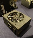
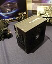
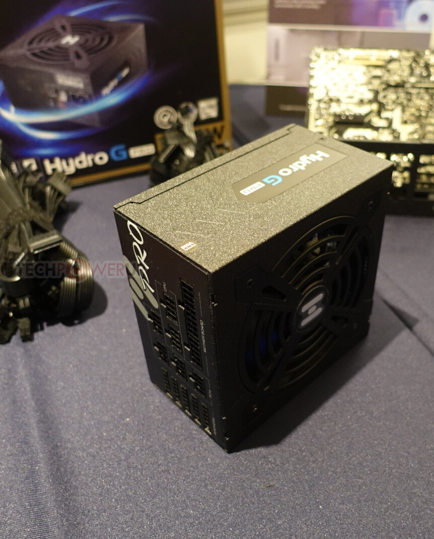
Fortron's consumer brand, FSP, brought a handful new power products to CES 2020, besides its already launched CMT710 premium gaming chassis, the Hydro G Pro premium modular PSU from mid-2019, and Dagger Pro SFX PSUs. The inconspicuous-looking FSP500-30AKB looks like a cheap OEM-included PSU with rear 80 mm exhaust, which comes included with your case, and which you immediately discard. Only that it's possibly the most innovative thing FSP brought to CES. This PSU is being designed for Intel's upcoming PC spec that does away with the 5 V, 5 Vsb, and 3.3 V power domains altogether.

The pure-12 V PSU has only two domains: +12 V and +12 Vsb. What this means is a goodbye to the bulky 24-pin ATX power connector. The PSU only feeds 12 V to your motherboard, which uses onboard VRM and DC-to-DC switching to put out the lower voltage domains, including power for your SATA storage devices. The 24-pin connector is effectively reduced to a new 10-pin connector that only has 12 V and 12 Vsb cabling. Other cables include 8-pin EPS connectors for your CPU VRM, and 6+2 pin PCIe connectors for your graphics cards. EPS and PCIe power are purely 12 V-based standards already. The 5-pin connector is less than half as thick as your 24-pin connector, and 2 pins wider than an EPS connector. Some of the more premium PSUs may user thicker gauge wires for this connector.
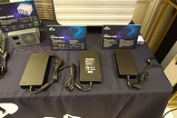
Next up is the Emergy 1000, a UPS dressed like a travel bag, with wheels, handle, and a plastic body to boot, which is ready to hit the road. It also has a lid with a bag-like zipper, which opens up a compartment where you tuck in its 3-pin AC cable. Inside is a sealed lead acid battery (and not lithium-ion), and a 1.5 kVA pure sine-wave AC inverter. The charging component pulls 600 W off the wall to rapidly recharge the battery (most 1.5 kVA UPSes pull around 150 W). Besides taking in 3-pin AC (100-240 VAC wide input range), the Emergy 1000 also takes in 12 V DC from third-party solar panels. Unfortunately, FSP didn't put out any official Ah figures for the battery.
Add your own comment

35 Comments on FSP at CES 2020: A Next-Gen Pure 12V PSU, and a UPS That Wants to See the World

#1
FordGT90Concept
"I go fast!1!11!1!"
Yes, I think it's time to rethink PSUs/motherboards but I think more VRM hardware should be moved to the PSU, not removed to the motherboard.
Posted on Reply
#2
silentbogo
FordGT90ConceptYes, I think it's time to rethink PSUs/motherboards but I think more VRM hardware should be moved to the PSU, not removed to the motherboard.
So you can have more ripple and larger voltage drop from all the wires? I think it's the right direction.
There are tons of existing proprietary solutions similar to this, from older SFFs to newest servers. Same approach: 12V&12VSB(or ~11VSB) from PSU and vregs on motherboard.
Given how efficient switching regulators nowadays are and how small the power usage is on +5V&3V rails, you can make everything with minimal PCB footprint and barely any heat.
And just like with new Mac Pro, or the old Fujitsu/Lenovo SFFs, if you need 5V/3.3V for peripherals - just hook it up to a motherboard power connector.
Posted on Reply
#3
FordGT90Concept
"I go fast!1!11!1!"
Because it gives more consumer choice in regards to efficiency and ease of repair should it fail. VRMs fail on a motherboard, you're looking at a big job to replace it.
Posted on Reply
#4
Valantar
Finally! I can't wait for the 24-pin to die its long awaited death. Should have happened a decade ago.
FordGT90ConceptBecause it gives more consumer choice in regards to efficiency and ease of repair should it fail. VRMs fail on a motherboard, you're looking at a big job to replace it.
DC-DC VRMs hardly ever fail. Besides, we're talking about voltage rails that hardly see load at all in modern devices, so any new vrm modules added to the board will be small and run cool. Moving to pure 12V input is one of the biggest improvements that can be made for modern PCs. It dramatically simplifies PSU design, simplifies motherboard design, increases conversion efficiency, simplifies unnecessarily complicated cabling, ditches legacy connectors and voltages, and has essentially zero drawbacks. It's not like it's an easy job to replace a failed VRM in your PSU either. Remember, modern PCs power everything important off 12V already, with both the CPU, PCIe and anything else power hungry using it. Sure, large and complex VRM setups on motherboards drive up cost and complexity, but this doesn't change that - we already have that. This just means we can do the same job with 14 less wires, and motherboard manufacturers can choose what to populate as legacy voltages fall out of use. This is purely a good thing. It would also be dead simple to make plug-in adapters converting this to classic 24-pin with all the required voltages (DC-ATX picoPSUs like this are quite common in the SFF PC space).
Posted on Reply
#5
EarthDog
FordGT90ConceptBecause it gives more consumer choice in regards to efficiency and ease of repair should it fail. VRMs fail on a motherboard, you're looking at a big job to replace it.
and when a psu fails, the average consumer can fix it?? Its rma time for both, bud. :)
Posted on Reply
#6
Valantar
btarunrThe pure-12 V PSU has only two domains: +12V and +12 Vsb. What this means is a goodbye to the bulky 24-pin ATX power connector. The PSU only feeds 12 V to your motherboard, which uses onboard VRM and DC-to-DC switching to put out the lower voltage domains, including power for your SATA storage devices. The 24-pin connector is effectively reduced to a new 10-pin connector that only has 12 V and 12 Vsb cabling. Other cables include 8-pin EPS connectors for your CPU VRM, and 6+2 pin PCIe connectors for your graphics cards. EPS and PCIe power are purely 12 V-based standards already. The 5-pin connector is less than half as thick as your 24-pin connector, and 2 pins wider than an EPS connector.
Some weird stuff here.
-You call it both a 10-pin and a 5-pin. I guess it's 10 in two rows of 5?
(-A side note: is it a "standard" mini-fit Jr connector like the 24-pin, EPS and PCIe, or a different style?)
-A 2x5-pin connector would be one pin wider than an 8-pin EPS, not two.
-By "less than half as thick", do you mean less than half as wide?

Also, any info on the cable pinout? Is it 4x12V, 1X12VSB, 5xGND, or something else?
Posted on Reply
#7
sutyi
EarthDogand when a psu fails, the average consumer can fix it?? Its rma time for both, bud. :)
It might just be me, but I would rather swap a PSU than a mobo.
Posted on Reply
#8
EarthDog
sutyiIt might just be me, but I would rather swap a PSU than a mobo.
Sure...but either way requires an RMA. Mortal humans do not fix these devices.
Posted on Reply
#9
Valantar
sutyiIt might just be me, but I would rather swap a PSU than a mobo.
Sure, but a barely used 12V-to-3.3V converter (or 5V) is highly unlikely to kill your motherboard. Failing PSUs tend to fail at components that see a lot of stress, after all.
Posted on Reply
#10
Dredi
FordGT90ConceptYes, I think it's time to rethink PSUs/motherboards but I think more VRM hardware should be moved to the PSU, not removed to the motherboard.
The transient response would be utter shit if the CPU vrm would be so far removed from the thing it’s powering. I’d also like to see the cabling required in order to feed a mere 9900k at full load of 166 amps (225W @ 1.35V). The EPS connector pins can take just 7 amps per pin, meaning that you would need a humongous 48 pin connector to feed that to the motherboard. Seems like a reasonable thing to do :-D
Posted on Reply
#11
DeathtoGnomes
If this type of PSU becomes the norm, I wonder if they can put the 5v regulator inline with the USB cable coming off the motherboard, meaning the mother has wont have to waste space on 5v/3.3v
--
silentbogoSo you can have more ripple and larger voltage drop from all the wires? I think it's the right direction.
There are tons of existing proprietary solutions similar to this, from older SFFs to newest servers. Same approach: 12V&12VSB(or ~11VSB) from PSU and vregs on motherboard.
Given how efficient switching regulators nowadays are and how small the power usage is on +5V&3V rails, you can make everything with minimal PCB footprint and barely any heat.
And just like with new Mac Pro, or the old Fujitsu/Lenovo SFFs, if you need 5V/3.3V for peripherals - just hook it up to a motherboard power connector.
I wonder how small regulators can go, like for something inline, maybe small enough not to affect aesthetics
Posted on Reply
#12
Dredi
DeathtoGnomesIf this type of PSU becomes the norm, I wonder if they can put the 5v regulator inline with the USB cable coming off the motherboard, meaning the mother has wont have to waste space on 5v/3.3v
--


I wonder how small regulators can go, like for something inline, maybe small enough not to affect aesthetics
Regulators can be super tiny for tiny loads. Inline regulator for USB is a bit difficult, as current full specification would call for a 100W 20V supply. If you mean just (legacy) usb 2.0, it would probably work inline without any problems, as only 2.5 W is required at 5 volts.
Posted on Reply
#13
Valantar
DrediRegulators can be super tiny for tiny loads. Inline regulator for USB is a bit difficult, as current full specification would call for a 100W 20V supply. If you mean just (legacy) usb 2.0, it would probably work inline without any problems, as only 2.5 W is required at 5 volts.
That's the USB-PD charger specification which doesn't apply to host devices, just docks, chargers, etc. IIRC host devices even for TB3 top out at 15W output.
Posted on Reply
#14
Dredi
ValantarThat's the USB-PD charger specification which doesn't apply to host devices, just docks, chargers, etc. IIRC host devices even for TB3 top out at 15W output.
Nothing states that a host device couldn’t act as a PD charger as well. Most high end motherboards already support PD or some similar standard to some extent and motherboard manufacturers offer expansion cards that support the full USB specification. It is just a matter of time before the full integration becomes common and I for one would like it if my PC could charge my phone at some meaningful speed.
Posted on Reply
#15
XL-R8R
There's so much talk of the new regulations, and barely any talk of that POWER SUPPLY/UPS IN A SUITCASE!! :roll: :roll: :roll:


Seeing such a thing gave me quite the smile earlier today when first reading this announcement. :lovetpu:
Posted on Reply
#16
silentbogo
FordGT90ConceptBecause it gives more consumer choice in regards to efficiency and ease of repair should it fail. VRMs fail on a motherboard, you're looking at a big job to replace it.
... and power supplies are ever-lasting, which means that 4 boxes of dead PSUs in my office are just a figure of my imagination.
Just think how much vdroop you need to compensate when supplying sub-1V to the modern CPU, if they move it to the PSU... and how thick the wiring should be to handle peak loads of ~100A even on consumer end of the market. That's ridiculous, and I'm not even gonna start on other minor rails.
Posted on Reply
#17
Assimilator
On the one hand I'm glad that the legacy rails are effectively going to go away, on the other I'm extremely disappointed that Intel didn't make it 24V or 48V which would allow for far less amps for the same watts, and hence thinner and cheaper wires and traces. All this boils down to is moving the 12V-to-other-rail circuitry from the PSU to the motherboard, which is hardly a great technological advancement - OEMs have done this for years.

I also have concerns about putting the 3.3V and 5V voltage regulator circuitry on the motherboard. Firstly, modern motherboards are crowded enough, where is that extra hardware going to live? Are low-end motherboards going to forgo this circuitry, and hence SATA ports, entirely? Secondly, if your motherboard fails and you're using Windows, you lose an activation (not Intel's fault, but definitely something to consider).
ValantarSure, but a barely used 12V-to-3.3V converter (or 5V) is highly unlikely to kill your motherboard. Failing PSUs tend to fail at components that see a lot of stress, after all.
But since the non-12V rails don't see a lot of use, they shouldn't see a lot of stress either. And most high-end PSUs simply derive these rails from 12V anyway.
Posted on Reply
#18
Valantar
AssimilatorBut since the non-12V rails don't see a lot of use, they shouldn't see a lot of stress either. And most high-end PSUs simply derive these rails from 12V anyway.
Exactly. Hence the argument of not wanting them on the motherboard for fear of them dying sand taking the motherboards with them is rather silly.
DrediNothing states that a host device couldn’t act as a PD charger as well. Most high end motherboards already support PD or some similar standard to some extent and motherboard manufacturers offer expansion cards that support the full USB specification. It is just a matter of time before the full integration becomes common and I for one would like it if my PC could charge my phone at some meaningful speed.
I'd love to have you show me a single host device that supports PD beyond 15W per port, as I have never seen one. I doubt there are many people out there wanting to charge their laptop from their desktop, after all. I could see the utility in running just a single cable to your monitor for power, video and USB, but that wouldn't work if the host was a laptop, so the monitor would need it's own PSU regardless. There are use cases, but they are niche use cases. Even VirtualLink maxes out at 15W (or was that 18? nvm).

Also: phone quick charging up until recent flagships has been <20W (there's a current arms race for ever higher amounts of watts for your quick charging, but most are still in the sub-20 range). 15W isn't too far from that, but 100W sure is. Just imagine the infrastructure if every type-C port on your PC (or laptop!) needed to be ble to supply 100W simultaneously. That would be insane! And let's not forget that 20V doesn't exist in desktop PCs, so any USB PCIe card supporting >60W output (12V5A) would need a boost converter on board to create that voltage. The same goes for 9V, which is currently the most common voltage for phone fast charging over USB-PD. Most PCs with PD output support only support a limited subset of its voltages and at reasonable amperages.
Posted on Reply
#19
DeathtoGnomes
DrediRegulators can be super tiny for tiny loads. Inline regulator for USB is a bit difficult, as current full specification would call for a 100W 20V supply. If you mean just (legacy) usb 2.0, it would probably work inline without any problems, as only 2.5 W is required at 5 volts.
if they cant adapt from themotherboards USB Port, I'd bet a molex could supply that 100W. I"m sure they could adapt.
AssimilatorI also have concerns about putting the 3.3V and 5V voltage regulator circuitry on the motherboard.
this is my line of thought.

I"m thinking the alternative would be to change USB standards to use 12v and force attached devices become responsible for converting whats needed for 5v or 3.3v or whatever. Thats still assuming this all changes to a pure 12v system.
Posted on Reply
#20
Dredi
ValantarExactly. Hence the argument of not wanting them on the motherboard for fear of them dying sand taking the motherboards with them is rather silly.


I'd love to have you show me a single host device that supports PD beyond 15W per port, as I have never seen one. I doubt there are many people out there wanting to charge their laptop from their desktop, after all. I could see the utility in running just a single cable to your monitor for power, video and USB, but that wouldn't work if the host was a laptop, so the monitor would need it's own PSU regardless. There are use cases, but they are niche use cases. Even VirtualLink maxes out at 15W (or was that 18? nvm).

Also: phone quick charging up until recent flagships has been <20W (there's a current arms race for ever higher amounts of watts for your quick charging, but most are still in the sub-20 range). 15W isn't too far from that, but 100W sure is. Just imagine the infrastructure if every type-C port on your PC (or laptop!) needed to be ble to supply 100W simultaneously. That would be insane! And let's not forget that 20V doesn't exist in desktop PCs, so any USB PCIe card supporting >60W output (12V5A) would need a boost converter on board to create that voltage. The same goes for 9V, which is currently the most common voltage for phone fast charging over USB-PD. Most PCs with PD output support only support a limited subset of its voltages and at reasonable amperages.
Something from 5 years ago:
www.asus.com/Motherboard-Accessories/USB-31-UPD-PANEL/
Phone chargers for some models are already up to 120W, which is a bit silly, but i sincerely think that the norm will be well over 15W for all flagships in a year or so.

Also I don’t think that it would be necessary to be able to output full 100W from all ports, as they could share the on board regulators to some extent. Like 250W max total over 8 ports or something like that.
Posted on Reply
#21
Valantar
DrediSomething from 5 years ago:
www.asus.com/Motherboard-Accessories/USB-31-UPD-PANEL/
Phone chargers for some models are already up to 120W, which is a bit silly, but i sincerely think that the norm will be well over 15W for all flagships in a year or so.

Also I don’t think that it would be necessary to be able to output full 100W from all ports, as they could share the on board regulators to some extent. Like 250W max total over 8 ports or something like that.
Looks like you found the one that exists, good work! But on a more serious note, providing 12V2A or even 12V3A through on-board USB-C should be somewhat feasible as long as max shared output doesn't go bonkers. The real problem though comes with each port needing a hefty power source and it's own power regulator - after all it's entirely possible to have a 5V device connected to one port, a 9V one to another and a 20V one to the third at the same time, so you can't run all ports off one regulator. (And you are arguing for full compatibility, after all.) Which would take up far too much space for a laptop at least, and likely a motherboard too. For your 8 ports at max 250W combined you'd need a motherboard with a 6-pin and an 8-pin PCIe for additional power (technically that's 225W,but let's be generous and borrow the rest from the 24-pin), plus eight voltage regulators (or in an alternative setup three regulators for the non-standard PC voltages in the USB-PD standard, each with a separate power plane in the motherboard, plus then some sort of voltage switching relay system per port). In short: this would be very bulky and complicated. And rather expensive.

On the other hand 24W (12V2A) or 27W (9V3A) is perfectly fine for fast charging any phone, no matter its capacity, and those >40W chargers are frankly just express speed battery charge cycle depletion devices with limited real world utility. Not to mention that none of those batteries can handle that amount of power fed into them for more than a brief while. Keeping host power delivery requirements is an eminently sensible thing to do, but I do see room for the spec to grow a bit in the future. Given that running multiple high power devices like this is also very unlikely it would be reasonable to cap shared output at something conservative like 5-6A.

Unless, of course, you want all your future motherboards to be SSI EEB form factor and $500 minimum.
Posted on Reply
#22
Dredi
ValantarLooks like you found the one that exists, good work! But on a more serious note, providing 12V2A or even 12V3A through on-board USB-C should be somewhat feasible as long as max shared output doesn't go bonkers. The real problem though comes with each port needing a hefty power source and it's own power regulator - after all it's entirely possible to have a 5V device connected to one port, a 9V one to another and a 20V one to the third at the same time, so you can't run all ports off one regulator. (And you are arguing for full compatibility, after all.) Which would take up far too much space for a laptop at least, and likely a motherboard too. For your 8 ports at max 250W combined you'd need a motherboard with a 6-pin and an 8-pin PCIe for additional power (technically that's 225W,but let's be generous and borrow the rest from the 24-pin), plus eight voltage regulators (or in an alternative setup three regulators for the non-standard PC voltages in the USB-PD standard, each with a separate power plane in the motherboard, plus then some sort of voltage switching relay system per port). In short: this would be very bulky and complicated. And rather expensive.

On the other hand 24W (12V2A) or 27W (9V3A) is perfectly fine for fast charging any phone, no matter its capacity, and those >40W chargers are frankly just express speed battery charge cycle depletion devices with limited real world utility. Not to mention that none of those batteries can handle that amount of power fed into them for more than a brief while. Keeping host power delivery requirements is an eminently sensible thing to do, but I do see room for the spec to grow a bit in the future. Given that running multiple high power devices like this is also very unlikely it would be reasonable to cap shared output at something conservative like 5-6A.

Unless, of course, you want all your future motherboards to be SSI EEB form factor and $500 minimum.
If we skip the 20V option at this point because it’s not efficient to produce, we would need just a new 9V regulator and a plane for that, everything else already exists on motherboards. A single 8pin eps gives 336W and two would suffice as a replacement for the 24 pin while providing silly amounts of power for all needs. Anyway, 12V over usb-pd would not need much investments as far as boards go, 9V just some regulator able to push out juice enough to saturate maybe two ports over a shared voltage plane. 5V is maybe the most expensive to add, but already exists on most motherboards to some extent in fast charge capability. I think we can fit a 8 amp 9V regulator even on boards smaller than EEB.
With the above we could have as many usb ports as we like and essentially unlimited amount could pump out 12V directly from the psu, two could pump out the maximum amps allowed for 9V and the 5V devices could share like 12 amps or so over a single voltage plane and a regulator. Each port would require an USB-PD voltage selector/amp monitoring chip (these are around 1$ a piece) to select the voltage plane and protect against shorts. The 5 and 9 V regulators at the specified amp ratings would cost maybe 5-10$ each. I fear that the usb-c connectors would be the most expensive components in this vision.

I do agree that supporting 20V over usb-pd with 12V power supplies is a bad idea as far as motherboards go.
Posted on Reply
#23
Valantar
DrediIf we skip the 20V option at this point because it’s not efficient to produce, we would need just a new 9V regulator and a plane for that, everything else already exists on motherboards. A single 8pin eps gives 336W and two would suffice as a replacement for the 24 pin while providing silly amounts of power for all needs. Anyway, 12V over usb-pd would not need much investments as far as boards go, 9V just some regulator able to push out juice enough to saturate maybe two ports over a shared voltage plane. 5V is maybe the most expensive to add, but already exists on most motherboards to some extent in fast charge capability. I think we can fit a 8 amp 9V regulator even on boards smaller than EEB.
With the above we could have as many usb ports as we like and essentially unlimited amount could pump out 12V directly from the psu, two could pump out the maximum amps allowed for 9V and the 5V devices could share like 12 amps or so over a single voltage plane and a regulator. Each port would require an USB-PD voltage selector/amp monitoring chip (these are around 1$ a piece) to select the voltage plane and protect against shorts. The 5 and 9 V regulators at the specified amp ratings would cost maybe 5-10$ each. I fear that the usb-c connectors would be the most expensive components in this vision.

I do agree that supporting 20V over usb-pd with 12V power supplies is a bad idea as far as motherboards go.
You're forgetting that USB-PD is also 15V. But even if we agree to also ditch 15V, limiting ourself to 60W max, how many amps can those selector chips handle? If they are doing the job of switching between voltage planes they also need to be capable of handling the maximum current passing through them. I kind of doubt a $1 chip is built to handle 5A or more continuously , but I could of course be wrong. (Also remember it can't just be a dumb PD negotiation chip, it also needs to handle passing through at least 10GBPs data and USB alt modes like DP). I've used a few of those dirt cheap PD receiver boards for DIY projects (so handy! And so cheap!), but those don't work for data transfer, just negotiate power delivery, so you'd need a much more advanced chip than that. Also, where would the extra voltage plane go on today's crowded motherboards? Remember, even a single added layer can drive up board costs dramatically. And remember how competitive the motherboard market is - even saving a dollar or two on the BOM is worth a lot to manufacturers. Not to mention that even ATX boards these days are stuffed to the gills, which will only get worse with DDR5 and PCIe 4.0/5.0. Fitting another voltage plane capable of handling a handful of amps, one or more powerful voltage regulators and a selector chip per port? All behind the rear I/O, where the CPU VRM usually lives? That sounds both expensive and very cramped. Would probably work well for a couple of ports on an add-in card like the one you shared, but it won't become standard any time soon. Also, any standard feature would need to scale down to ITX size, which... well, just no. Not happening.
Posted on Reply
#24
eidairaman1
The Exiled Airman
Might aswell just have a nuc (ftl)
Posted on Reply
#25
Dredi
ValantarYou're forgetting that USB-PD is also 15V. But even if we agree to also ditch 15V, limiting ourself to 60W max, how many amps can those selector chips handle? If they are doing the job of switching between voltage planes they also need to be capable of handling the maximum current passing through them. I kind of doubt a $1 chip is built to handle 5A or more continuously , but I could of course be wrong. (Also remember it can't just be a dumb PD negotiation chip, it also needs to handle passing through at least 10GBPs data and USB alt modes like DP). I've used a few of those dirt cheap PD receiver boards for DIY projects (so handy! And so cheap!), but those don't work for data transfer, just negotiate power delivery, so you'd need a much more advanced chip than that. Also, where would the extra voltage plane go on today's crowded motherboards? Remember, even a single added layer can drive up board costs dramatically. And remember how competitive the motherboard market is - even saving a dollar or two on the BOM is worth a lot to manufacturers. Not to mention that even ATX boards these days are stuffed to the gills, which will only get worse with DDR5 and PCIe 4.0/5.0. Fitting another voltage plane capable of handling a handful of amps, one or more powerful voltage regulators and a selector chip per port? All behind the rear I/O, where the CPU VRM usually lives? That sounds both expensive and very cramped. Would probably work well for a couple of ports on an add-in card like the one you shared, but it won't become standard any time soon. Also, any standard feature would need to scale down to ITX size, which... well, just no. Not happening.
www.ti.com/lit/ds/slvsf34/slvsf34.pdf
This one would be $2 and I’m sure there are cheaper options available. You just pass through the cc pins to it and it handles the power delivery independently from the other communication stuff already present with any usb3.x host controller. 5A max. Ddr5 and pcie4+ already make extra layers necessary, but which are not really needed in the IO area, giving us much needed real estate to apply the extra chips and power planes. It would cost a bit extra, but not that much. Itx would be a problem space wise, if you would wish to have anything but a few usb-c ports at the back.
Posted on Reply
Add your own comment
Apr 18th, 2024 21:58 EDT change timezone

New Forum Posts

Popular Reviews

Controversial News Posts