Monday, June 7th 2021

AMD Raphael CPU IHS Features Cutouts for Capacitors

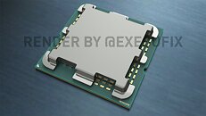
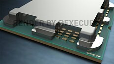
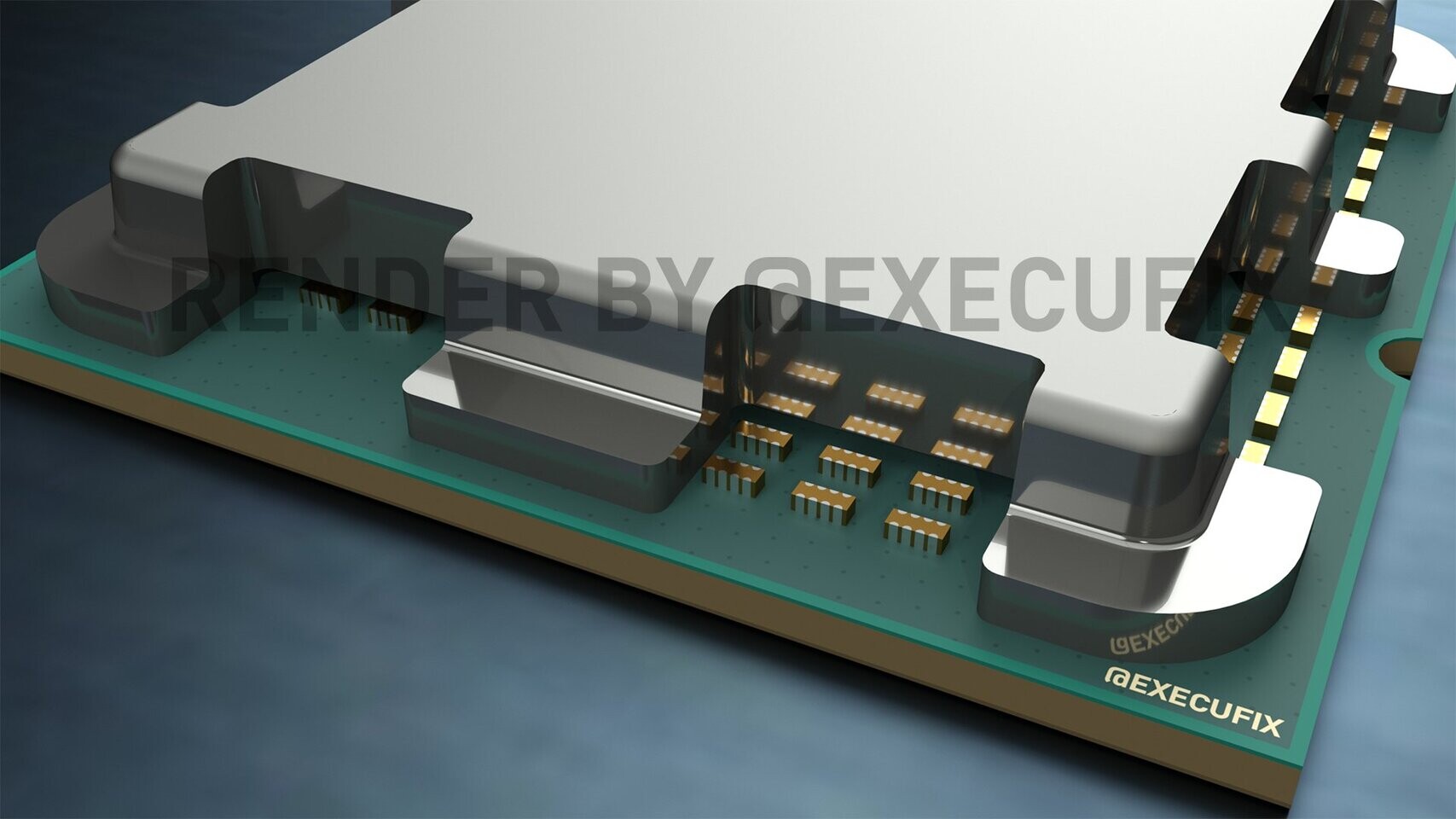
Last week,we have covered the leak of AMD's upcoming Raphael processor integrated heat spreader (IHS), which featured a rather unique design. While we have made speculations as to why the design was made like that, it seems that we now have an answer to the question. It was previously believed that the unique IHS design was there to protect a double-substrate design, like Intel designed with Skylake-X. However, thanks to the updated design by ExecutableFix, we now know that AMD's design choice for Raphael is based on the simple fact that the IHS needs those cutouts for capacitors, as this seems to be the only place to have them.

As you can see below, there was no room on the LGA side, where the LGA pads are placed, and a lot of speculation suggested that capacitors were placed under the IHS or in IHS cutouts. The latter has proven to be the case according to this leak. You can check out some of the updated renderings in the images below.
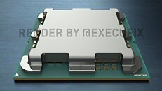
Source: ExecutableFix (Twitter)
Add your own comment

21 Comments on AMD Raphael CPU IHS Features Cutouts for Capacitors

#1
Caring1
So I guess conductive TIM is out of the question.
Posted on Reply
#2
Arcdar
I might have a Déjà-vu but wasn't that already posted last week?
Posted on Reply
#3
mtcn77
Caring1So I guess conductive TIM is out of the question.
We can still expect integrated vapor chamber in the cold plate. The price will skyrocket, but sooner or later it will paint itself into the frame.
Posted on Reply
#5
Caring1
The first person to delid one of these deserves a bravery medal. :eek:
Posted on Reply
#7
dj-electric
These sort of machined IHS's will probably be expensive to make. Sheeesh
Posted on Reply
#8
DeathtoGnomes
Caring1The first person to delid one of these deserves a bravery medal. :eek:
I think a dremel would do well, but I'm sure you're implying removing the IHS as a whole.
ArcdarI might have a Déjà-vu but wasn't that already posted last week?
did you read this, its a correction of sorts about last weeks leak
Posted on Reply
#9
Legacy-ZA
Caring1So I guess conductive TIM is out of the question.
My first thought too, not too sure how I would feel about covering it up with nail polish or something similar.
Posted on Reply
#10
stimpy88
An odd choice considering that the AM5 platform has just been designed from the ground up, a few extra millimetres of extra space would have negated the need for an elaborate IHS, and would have also resulted in many more pins being available for a few more PCIE lines for instance... Strange.
Posted on Reply
#11
R0H1T
Take this with loads of salt ~ I mean more than a handful "Cough Cough" :D
Posted on Reply
#12
Dredi
Caring1So I guess conductive TIM is out of the question.
These will most likely be soldered on with conductive tim just like the previous heat spreaders.

Absolutely nothing suggests otherwise.

as for using conductive tim on top, nothing has changed, it’s fatal anyway if something drips onto the motherboard. Now it can also drip to the cpu itself, but the difference is very minor in terms of over applying.
Posted on Reply
#13
Vya Domus
Caring1So I guess conductive TIM is out of the question.
You can just put tape over the capacitors.
Posted on Reply
#14
TheDeeGee
I feel for the testers, having to clean paste :P
Posted on Reply
#15
delshay
That design allows the capacitors to perform better. Capacitors are sensitive to heat. Not having it trapped under the IHS allows it to breathe better. Performance will be marginal, very small, so you may not even notice it.. . ..See/read PDF Docs on ceramic capacitors.

EDIT: On the other hand, the IHS has lost a little bit of mass, ...Hmmm
Posted on Reply
#16
Operandi
stimpy88An odd choice considering that the AM5 platform has just been designed from the ground up, a few extra millimetres of extra space would have negated the need for an elaborate IHS, and would have also resulted in many more pins being available for a few more PCIE lines for instance... Strange.
The closer the caps are to the logic the better so a few mm might count here.
Posted on Reply
#17
delshay
Caring1The first person to delid one of these deserves a bravery medal. :eek:
It's going to be much harder to delid because if the glue is located just behind the capacitor how do you gain access. You can't even get a razer blade in there to loosen/separate the glue between the IHS & PCB. Melting the indium on the die is not a problem, but if it requires higher than normal temperature to break down the glue, then it's a problem.
Posted on Reply
#18
GoldenX
This will be hell to clean.
Posted on Reply
#19
delshay
Like to point out one more danger even if you successfully delid. Because the capacitors are so near to the IHS, if you reuse the IHS without gluing it down, if the IHS moves in any direction you will have a short circuit across the capacitor(s).
Posted on Reply
#20
stimpy88
OperandiThe closer the caps are to the logic the better so a few mm might count here.
That's not what I mean...

If they made the whole package a couple of millimetres larger, then the caps would have fit under the IHS. Remember, AMD just designed this new socket themselves. I personally think this is a design oversight.
Posted on Reply
#21
Operandi
GoldenXThis will be hell to clean.
Oh, and keep the caps in the center of the package... Yeah, idk must be a reason, keep the trace lengths as short as possible maybe? Its definitely not a design oversight, these types of design decisions were made a year ago or more, and too many people involved for it to just be a mistake.
Posted on Reply
Add your own comment
Apr 25th, 2024 11:45 EDT change timezone

New Forum Posts

Popular Reviews

Controversial News Posts