A Detailed Look Into PSUs |
|
Switching Regulator Topologies used in Contemporary PSUs


According to the peak current that will pass from the main switches, the desired efficiency levels, the maximum operating voltage across the switches the cost etc. a manufacturer has several switching regulator topologies at his disposal.
Below you will find a table that compares several switching regulator topologies (Marty Brown: Power Supply Cookbook)
| Topology | Power Range | Vin (DC) Range | Primary/Secondary Isolation | Typical Efficiency | Relative Cost |
|---|---|---|---|---|---|
| Buck | 0-1000 W | 5-40 V | No | 78% | 1.0 |
| Boost | 0-150 W | 4-40 V | No | 80% | 1.0 |
| Buck-Boost | 0-150 W | 5-40 V | No | 80% | 1.0 |
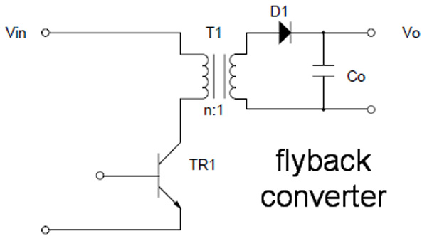
| Flyback | 0-150 W | 5-500 V | Yes | 80% | 1.2 |
| Resonant Forward | 0-60 W | 60-400 V | Yes | 87% | 1.2 |
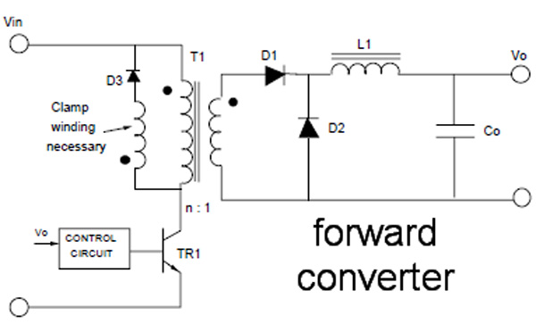
| 1T forward | 0-150 W | 5-500 V | Yes | 78% | 1.4 |
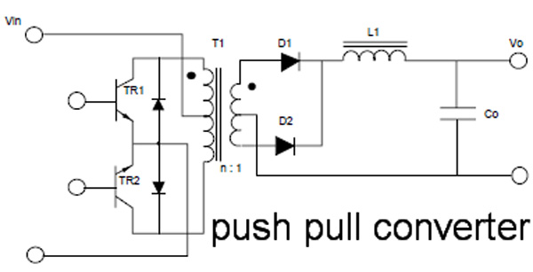
| Push-Pull | 100-1000 W | 50-1000 V | Yes | 75% | 2.0 |
| Half-bridge | 100-500 W | 50-1000 V | Yes | 75% | 2.2 |
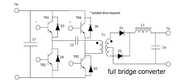
| Full-bridge | 400-2000+ W | 50-1000 V | Yes | 73% | 2.5 |
| Quasi Resonant | 100-1000+ W | 50-1000 V | Yes | 87-92% | 2.8 |
Finally, here you will find a very informative pdf file that describes many commonly used topologies.
Apr 23rd, 2024 15:40 EDT
change timezone
Latest GPU Drivers
New Forum Posts
- windows 11 (3)
- Which new games will you be buying? (299)
- Meta Horizon OS (5)
- No POST, and no display (6)
- need help with motherboard/ ram compability certainty (5)
- My computer setup - Request for opinions (11)
- EK seems to be having major issues (26)
- DeepCool AIO LS720 RGB NOT WORKING HELP! (0)
- Is there a technical reason that Windows 11 doesn't have built into it battery charge limitation? (36)
- What's your latest tech purchase? (20300)
Popular Reviews
- Horizon Forbidden West Performance Benchmark Review - 30 GPUs Tested
- Fractal Design Terra Review
- Corsair 2000D Airflow Review
- Thermalright Phantom Spirit 120 EVO Review
- Minisforum EliteMini UM780 XTX (AMD Ryzen 7 7840HS) Review
- ASUS GeForce RTX 4090 STRIX OC Review
- NVIDIA GeForce RTX 4090 Founders Edition Review - Impressive Performance
- ASUS GeForce RTX 4090 Matrix Platinum Review - The RTX 4090 Ti
- Creative Pebble X Plus Review
- MSI GeForce RTX 4090 Gaming X Trio Review
Controversial News Posts
- Sony PlayStation 5 Pro Specifications Confirmed, Console Arrives Before Holidays (116)
- NVIDIA Points Intel Raptor Lake CPU Users to Get Help from Intel Amid System Instability Issues (105)
- AMD "Strix Halo" Zen 5 Mobile Processor Pictured: Chiplet-based, Uses 256-bit LPDDR5X (101)
- US Government Wants Nuclear Plants to Offload AI Data Center Expansion (98)
- Windows 10 Security Updates to Cost $61 After 2025, $427 by 2028 (84)
- Developers of Outpost Infinity Siege Recommend Underclocking i9-13900K and i9-14900K for Stability on Machines with RTX 4090 (84)
- TechPowerUp Hiring: Reviewers Wanted for Motherboards, Laptops, Gaming Handhelds and Prebuilt Desktops (74)
- Intel Realizes the Only Way to Save x86 is to Democratize it, Reopens x86 IP Licensing (70)