Shuttle AN35N-Ultra Voltmods |
|
|
Author: celemine1Gig
Date: 2004-07-19 17:39:55
|
|
I used the following parts for my mods:
Afterwards, adjust all potentiometers to the maximum resistance, because that’s the value to start with - this is very important!
http://www.richtek-ic.com.tw/Product/Docs/DS9241AB-02%283%29.pdf
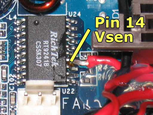
Connect the outer pin of the 50K potentiometer to Pin #14 (Vsen) of the RT9241B chip and then connect the middle contact of the potentiomter to Ground.
Pin #13 of the RT9241B is a ground pin, but I felt that it was too cramped for me to solder the two cables next to each other. I used a thicker cable than I normally would, because I had read that it would give more stable VCore values in comparison to using a thinner wire (reference to Hell-Fire’s postings on XtremeSystems). In order to ground the middle pin of the poti, I just put the cable through a hole in the PCB, just next to the P4-connector on the motherboard. On the backside of the mainboard, I connected the cable to one of the two ground pins of the P4-connector.


http://www.richtek-ic.com.tw/Product/Docs/DS9203A-06P%281%29.pdf
Connect the outer pin of the 20K potentiometer to Pin #8 (FB) of the RT9203 chip. Then connect the potentiometer's middle contact to Pin #3 (Ground/GND) on RT9203.
Measuring point for VDD is the right leg of the mosfet directly under (righthand) the RT9203 chip.

http://www.national.com/JPN/ds/LM/LM431.pdf
The outer pin of the 5K potentiometer needs to be connected to LM431's Pin #8 (Reference). After that you have to connect the middle pin of the potentiomter to ground. Since the LM431 chip does not have a Ground/GND-Pin (NC is NOT Ground), you willl have to think about something different. I used a longer, thicker wire again and put this wire through the second hole in the PCB, next to the P4-connector (routed the wire along the backside of the AGP-port). Then, like with the VCore-Mod, just connect the wire to the second ground point of the P4 Connector.
Measuring point for Vdimm is the left leg of the mosfet directly next (lefthand) to the first Dimm-slot (have a look at the pics).


That’s all the info needed to do the mods!
P.S.: I did the following additional modifications to my board:
Warning:
All modifications are done at your own risk! I am not responsible for any damage caused by the mods!
- one 50K (trimmer-) potentiometer for the VCore-Mod
- one 20K (trimmer-) potentiometer for the VDD-Mod
- one 5K (trimmer-) Potentiometer for the VDimm-Mod
- a good soldering iron (Ersa 25W in my case)
- rosin core solder and a resin (for example „colophony“)
- some heatshrink tubing and hotglue
- and perhaps some isolating protection lacquer
Afterwards, adjust all potentiometers to the maximum resistance, because that’s the value to start with - this is very important!
VCore-Mod
Datasheet of the chip:http://www.richtek-ic.com.tw/Product/Docs/DS9241AB-02%283%29.pdf
Connect the outer pin of the 50K potentiometer to Pin #14 (Vsen) of the RT9241B chip and then connect the middle contact of the potentiomter to Ground.
Pin #13 of the RT9241B is a ground pin, but I felt that it was too cramped for me to solder the two cables next to each other. I used a thicker cable than I normally would, because I had read that it would give more stable VCore values in comparison to using a thinner wire (reference to Hell-Fire’s postings on XtremeSystems). In order to ground the middle pin of the poti, I just put the cable through a hole in the PCB, just next to the P4-connector on the motherboard. On the backside of the mainboard, I connected the cable to one of the two ground pins of the P4-connector.
VDD-Mod
Datasheet of the chip:http://www.richtek-ic.com.tw/Product/Docs/DS9203A-06P%281%29.pdf
Connect the outer pin of the 20K potentiometer to Pin #8 (FB) of the RT9203 chip. Then connect the potentiometer's middle contact to Pin #3 (Ground/GND) on RT9203.
Measuring point for VDD is the right leg of the mosfet directly under (righthand) the RT9203 chip.
VDimm-Mod
Datasheet of the chip:http://www.national.com/JPN/ds/LM/LM431.pdf
The outer pin of the 5K potentiometer needs to be connected to LM431's Pin #8 (Reference). After that you have to connect the middle pin of the potentiomter to ground. Since the LM431 chip does not have a Ground/GND-Pin (NC is NOT Ground), you willl have to think about something different. I used a longer, thicker wire again and put this wire through the second hole in the PCB, next to the P4-connector (routed the wire along the backside of the AGP-port). Then, like with the VCore-Mod, just connect the wire to the second ground point of the P4 Connector.
Measuring point for Vdimm is the left leg of the mosfet directly next (lefthand) to the first Dimm-slot (have a look at the pics).
Overview

That’s all the info needed to do the mods!
P.S.: I did the following additional modifications to my board:
- Hardware-L12-Mod (used the How-To from http://www.ocinside.de/html/workshop/pinmod/amd_pinmod_d.html).

- additional cabling to connect a second PSU

- Northbridge and Southbridge were lapped and I put heatsinks on all those chips that I thought would benefit from it

Warning:
All modifications are done at your own risk! I am not responsible for any damage caused by the mods!
Apr 25th, 2024 03:38 EDT
change timezone
Latest GPU Drivers
New Forum Posts
- The TPU UK Clubhouse (24785)
- Github comments used to push malware via Microsoft repo urls (3)
- Bizarre Throttlestop issue (5)
- Core i5-6300U (13)
- GTX 1070 Ti - TDP Issues - Always Power Throttling (5)
- What phone you use as your daily driver? And, a discussion of them. (1471)
- (Anti) SFF fun house (349)
- What's your latest tech purchase? (20337)
- The Official Linux/Unix Desktop Screenshots Megathread (694)
- XFX RX470 8GB no video and error 43 (27)
Popular Reviews
- Fractal Design Terra Review
- Thermalright Phantom Spirit 120 EVO Review
- Corsair 2000D Airflow Review
- Minisforum EliteMini UM780 XTX (AMD Ryzen 7 7840HS) Review
- ASUS GeForce RTX 4090 STRIX OC Review
- NVIDIA GeForce RTX 4090 Founders Edition Review - Impressive Performance
- ASUS GeForce RTX 4090 Matrix Platinum Review - The RTX 4090 Ti
- MSI GeForce RTX 4090 Suprim X Review
- MSI GeForce RTX 4090 Gaming X Trio Review
- Gigabyte GeForce RTX 4090 Gaming OC Review
Controversial News Posts
- Sony PlayStation 5 Pro Specifications Confirmed, Console Arrives Before Holidays (116)
- NVIDIA Points Intel Raptor Lake CPU Users to Get Help from Intel Amid System Instability Issues (106)
- AMD "Strix Halo" Zen 5 Mobile Processor Pictured: Chiplet-based, Uses 256-bit LPDDR5X (101)
- US Government Wants Nuclear Plants to Offload AI Data Center Expansion (98)
- Windows 10 Security Updates to Cost $61 After 2025, $427 by 2028 (84)
- Developers of Outpost Infinity Siege Recommend Underclocking i9-13900K and i9-14900K for Stability on Machines with RTX 4090 (84)
- TechPowerUp Hiring: Reviewers Wanted for Motherboards, Laptops, Gaming Handhelds and Prebuilt Desktops (78)
- AMD's RDNA 4 GPUs Could Stick with 18 Gbps GDDR6 Memory (74)