- Joined
- Sep 2, 2009
- Messages
- 125 (0.02/day)
- Location
- New Hampshire, USA
I was very fortunate to have been commissioned to build a large wooden tower case, to be used to hold a very large water cooled rig. Here's the design drawings:


The case is designed to contain an EATX motherboard, seven 5.25-inch drives and eight 3.5-inch hard drives. Two 120.4 radiators will eventually be mounted in the top chamber:

For wire routing/hiding, there's a "false back" between the mother board tray and the side panel:

The front fascia/panel is removable (although not on a hinge). Each horizontal "chamber" in the case is fed and exhausted by a 120mm fan.

Fresh air is supplied to the front fans via a bottom-fed, built-in air duct.

The first order of business was to fabricate the hard drive cages from 1/8-inch aluminum flat bar:

The drives are suspended in soft rubber grommets:

The cage/rails for the 5.25-inch optical drives were made from 1/8-inch aluminum sheet and 1/2-inch aluminum angle. The aluminum sheet was easily cut on the table saw (fitted with a carbide tipped saw blade). The strips were then stacked and a full-size template of a rail (drawn in Sketchup) was taped on.

The strips were then clamped to a home made jig in order to cut the slots in the rails safely and accurately.

In the center edge of each rail, a 6-32 thread was tapped (using my awesome hand tapper):

The holes in the angle were quickly drilled with the help of a self-centering vice (note the addition of a 1/8-inch plate in order to center the "leg" of the angle in the vice):

All of the aluminum pieces were scratched with 80-grit sandpaper. One-half of an assembled drive cage:

Having the ability to remove individual drive rails provides added flexibility when it comes to laying out the rig and for easy customizations.
A couple of templates were fabricated from some MDF. These were used to route out the motherboard tray and power supply openings out of the back panel.
Power supply template:

Motherboard tray template:


The frame for the back panel:

A jig was built to safely rabbet the inside edges of the glued-up front panel frame.

The front and back panel frames were rabbeted to accept the 5.2mm oak veneer plywood.


The plywood was cut on the table saw. The corners were rounded "free hand" on the table saw then finished with sandpaper and a sanding block:

A cleat was glued to the backside of the MB tray template for easy alignment.


A router with a 1/2-inch pattern/flush-trim bit was used to route out the hole. For the top and bottom power supply holes, that template was fastened to the underside of the panel in order to center it properly and a 3/8-inch pattern/flush-trim bit was used.


The "shelves" that separate the case into three chambers was fab'd from 3/4-inch square oak, rabbeted to hide the plywood edge.

The shelves nestle onto brackets made from 1/2-inch aluminum angle.

The angle bracket for the top shelf along the back panel just so happened to land in the same location as the bolts used to fasten the motherboard tray. Originally I was thinking the tray would be bolted onto the back panel (with a nut), but with the angle bracket right there, doing so would be very awkward. So instead, I just tapped some 6-32 threads.

 :up:
:up:
I didn't like the quality of the front panel's plywood "B" side (the good "A" side faces the inside of the case), so I had to cut another piece and sandwich them together, "B" side to "B" side. By utilizing the existing panel as a template for my router, this extra task went fast. After rough cutting another piece of plywood, the two pieces were temporarily held together with double-sided tape. Then a pattern/flush trim router bit was used to "cut" the panel to size.

The hole for the optical drives was routed out and the corners squared with a hand file.


The next task was to route three 120mm holes in the front panel, but I discovered that the fan frame I was going to use as a router template wasn't stiff enough, which would have resulted in misshaped holes.
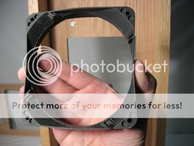
The simple fix will be to glue on some 1/8-inch aluminum flat bar to stiffen it.

There wasn't an easy way to fasten the fan "template" to the front panel safely, so I decided to fabricate yet another template. I cut some 1/4-inch thick plywood the same size as the front panel and I aligned the fan housing and used it as a guide to drill some holes (through all three layers of plywood).

The plywood template was removed and the fan housing was "bolted" to it with some #8 socket cap screws i.e. the bolts were used to cut their own threads into the plywood.

The plywood with the bolted-on fan were placed onto the workbench and a 1/2-inch pattern/flush router bit was used to cut out the fan holes:

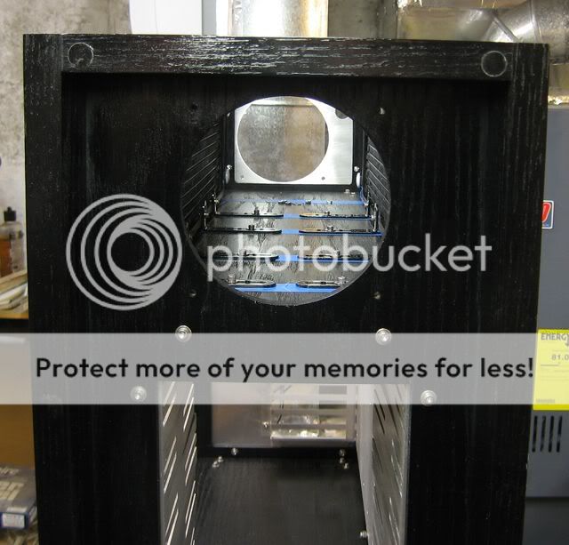
After all three holes were cut out of the template, the template was attached to the front panel and three more holes were routed out of it.

The template was removed and the holes were cleaned-up with some 120 grit sandpaper.

The top of the case is made from 1/4-inch plywood edged with 3/4 x 1-1/4-inch oak. The plywood was roughly cut to size on the table saw and then a couple of extra layers of plywood were glued to the edges in order to thicken it in preparation for gluing the 3/4-inch edging.

The top was then trimmed to the desired width with the router.

The edging was glued, scraped flush with a cabinet scraper and lightly sanded.


The ends of the top were cut with... Anyone? Anyone? ...a router fitted with a flush/trim bit. The "jig" used to make sure the cut was nice and square was a framing square taped to the workbench.

Completed top:


The side panels are made from 1/4-inch oak veneer plywood, edged with 3/4-inch oak, mitered at the corners. The plywood sits in a 5.2x10mm deep groove.


Between the motherboard tray and the side panel is a removable "false" back that will strengthen the case, steady the motherboard tray and conceal all of the wiring. There is about 1-1/4 inches between the "false" back and the side panel.


During the construction of the external drive cage, a couple of drill bits were used to align everything, just to make sure both pieces were identical.

Yet another feature of this case is that each of the drive rails can be removed for easy modding and/or for a custom configuration.


I decided to fasten the top to the case with some 'T'-nuts, but I didn't have any lying around the shop so I fabricated a simple "plate"-nut. A plate-nut is just a 1/8-inch thick piece of aluminum flat bar, taped for 6-32 bolts. The nut was bolted to a dual layer of 1/4-inch plywood which was then glued to the top. Hard to describe, but very simple to make.


In order to accurately determine where to drill the corresponding holes in the front frame, I made some pointy marking thingies from a couple of bolts.

The top with the pointy thingies were then pressed down onto the case, indicating where to drill.

Perfect alignment!
The side panels are held onto the case via four magnetic catches.

I'm quite pleased with the holding power of these babies. They were eventually painted black.

The base molding is just a piece of 3/4x3-inch red oak that extends out from underneath the entire case by 3/8-inch. Adding the bottom molding really helped to balance the case visually.

Holes large enough to ventilate quad radiators were routed out of both side panels. Perforated aluminum sheet (0.063" thick, 0.1875" dia. holes, 0.25" stagger) was then temporarily applied.


To fasten the front panel to the case I wanted to use a more elegant/unobtrusive mechanism. I decided on attaching it with some powerful rare earth magnets (1/2" dia. x 1/8" thick; grade N52; black nickel plated).

Two magnets (for double the holding power) were super-glued flush into the case, around all four corners.

Steel washers were glued flush around the front panel.

Alignment/guide blocks were also glued to the inside of the panel.

And two grooves were routed out of the top of the panel so headset wires, etc. have a place to pass through.

I thought it was too difficult to unscrew/screw the screws that fasten the false backs to the shelves without stripping them, so I went ahead and installed some brass threaded inserts for #6-32 bolts.

In the picture above, you can also see a 1/2-inch spacer that is used to fasten the removable motherboard tray to the false back.
The back was modified with a slot along its bottom and another at the top (for an 8-pin power lead).


From the inside of the case, you can see how the bottom slot straddles the bottom edge of the motherboard tray perfectly.

I bolted casters (twin-wheel with hood, 2-3/8" nylon wheels) to the bottom of the separate molding piece, which elevated the case 5/8-inch up off the floor.


I fabricated the aluminum power supply mounting plate using a plate from another case as a pattern. The pattern was used to guide my router fitted with a 1/4-inch carbide pattern bit:

A plate for the power switch and an intake fan was also routed out of aluminum, via a custom made template:

The final results:


To help support the power supply I fabricated some posts made from a rubber bumper, 1/2-inch spacer and some nuts on a 6-32 socket cap screw:

The hard drive cages are too tall to remove them from the case without having to first remove the entire lower shelf. To help ease that burden I devised a three-point mounting system whereby the cage is held tight to the bottom of the case via a center post and two socket cap screws.
The hard drive cage's center support was drilled to have just a half a circle via a sacrificial piece of angle material:


Last pics before stain and finish were applied:


Final pics!


The case is designed to contain an EATX motherboard, seven 5.25-inch drives and eight 3.5-inch hard drives. Two 120.4 radiators will eventually be mounted in the top chamber:
For wire routing/hiding, there's a "false back" between the mother board tray and the side panel:
The front fascia/panel is removable (although not on a hinge). Each horizontal "chamber" in the case is fed and exhausted by a 120mm fan.
Fresh air is supplied to the front fans via a bottom-fed, built-in air duct.
The first order of business was to fabricate the hard drive cages from 1/8-inch aluminum flat bar:
The drives are suspended in soft rubber grommets:
The cage/rails for the 5.25-inch optical drives were made from 1/8-inch aluminum sheet and 1/2-inch aluminum angle. The aluminum sheet was easily cut on the table saw (fitted with a carbide tipped saw blade). The strips were then stacked and a full-size template of a rail (drawn in Sketchup) was taped on.
The strips were then clamped to a home made jig in order to cut the slots in the rails safely and accurately.
In the center edge of each rail, a 6-32 thread was tapped (using my awesome hand tapper):
The holes in the angle were quickly drilled with the help of a self-centering vice (note the addition of a 1/8-inch plate in order to center the "leg" of the angle in the vice):
All of the aluminum pieces were scratched with 80-grit sandpaper. One-half of an assembled drive cage:
Having the ability to remove individual drive rails provides added flexibility when it comes to laying out the rig and for easy customizations.
A couple of templates were fabricated from some MDF. These were used to route out the motherboard tray and power supply openings out of the back panel.
Power supply template:
Motherboard tray template:
The frame for the back panel:
A jig was built to safely rabbet the inside edges of the glued-up front panel frame.
The front and back panel frames were rabbeted to accept the 5.2mm oak veneer plywood.
The plywood was cut on the table saw. The corners were rounded "free hand" on the table saw then finished with sandpaper and a sanding block:
A cleat was glued to the backside of the MB tray template for easy alignment.
A router with a 1/2-inch pattern/flush-trim bit was used to route out the hole. For the top and bottom power supply holes, that template was fastened to the underside of the panel in order to center it properly and a 3/8-inch pattern/flush-trim bit was used.
The "shelves" that separate the case into three chambers was fab'd from 3/4-inch square oak, rabbeted to hide the plywood edge.
The shelves nestle onto brackets made from 1/2-inch aluminum angle.
The angle bracket for the top shelf along the back panel just so happened to land in the same location as the bolts used to fasten the motherboard tray. Originally I was thinking the tray would be bolted onto the back panel (with a nut), but with the angle bracket right there, doing so would be very awkward. So instead, I just tapped some 6-32 threads.
I didn't like the quality of the front panel's plywood "B" side (the good "A" side faces the inside of the case), so I had to cut another piece and sandwich them together, "B" side to "B" side. By utilizing the existing panel as a template for my router, this extra task went fast. After rough cutting another piece of plywood, the two pieces were temporarily held together with double-sided tape. Then a pattern/flush trim router bit was used to "cut" the panel to size.
The hole for the optical drives was routed out and the corners squared with a hand file.
The next task was to route three 120mm holes in the front panel, but I discovered that the fan frame I was going to use as a router template wasn't stiff enough, which would have resulted in misshaped holes.
The simple fix will be to glue on some 1/8-inch aluminum flat bar to stiffen it.
There wasn't an easy way to fasten the fan "template" to the front panel safely, so I decided to fabricate yet another template. I cut some 1/4-inch thick plywood the same size as the front panel and I aligned the fan housing and used it as a guide to drill some holes (through all three layers of plywood).
The plywood template was removed and the fan housing was "bolted" to it with some #8 socket cap screws i.e. the bolts were used to cut their own threads into the plywood.
The plywood with the bolted-on fan were placed onto the workbench and a 1/2-inch pattern/flush router bit was used to cut out the fan holes:
After all three holes were cut out of the template, the template was attached to the front panel and three more holes were routed out of it.
The template was removed and the holes were cleaned-up with some 120 grit sandpaper.
The top of the case is made from 1/4-inch plywood edged with 3/4 x 1-1/4-inch oak. The plywood was roughly cut to size on the table saw and then a couple of extra layers of plywood were glued to the edges in order to thicken it in preparation for gluing the 3/4-inch edging.
The top was then trimmed to the desired width with the router.
The edging was glued, scraped flush with a cabinet scraper and lightly sanded.
The ends of the top were cut with... Anyone? Anyone? ...a router fitted with a flush/trim bit. The "jig" used to make sure the cut was nice and square was a framing square taped to the workbench.
Completed top:
The side panels are made from 1/4-inch oak veneer plywood, edged with 3/4-inch oak, mitered at the corners. The plywood sits in a 5.2x10mm deep groove.
Between the motherboard tray and the side panel is a removable "false" back that will strengthen the case, steady the motherboard tray and conceal all of the wiring. There is about 1-1/4 inches between the "false" back and the side panel.
During the construction of the external drive cage, a couple of drill bits were used to align everything, just to make sure both pieces were identical.
Yet another feature of this case is that each of the drive rails can be removed for easy modding and/or for a custom configuration.
I decided to fasten the top to the case with some 'T'-nuts, but I didn't have any lying around the shop so I fabricated a simple "plate"-nut. A plate-nut is just a 1/8-inch thick piece of aluminum flat bar, taped for 6-32 bolts. The nut was bolted to a dual layer of 1/4-inch plywood which was then glued to the top. Hard to describe, but very simple to make.
In order to accurately determine where to drill the corresponding holes in the front frame, I made some pointy marking thingies from a couple of bolts.
The top with the pointy thingies were then pressed down onto the case, indicating where to drill.
Perfect alignment!
The side panels are held onto the case via four magnetic catches.
I'm quite pleased with the holding power of these babies. They were eventually painted black.
The base molding is just a piece of 3/4x3-inch red oak that extends out from underneath the entire case by 3/8-inch. Adding the bottom molding really helped to balance the case visually.
Holes large enough to ventilate quad radiators were routed out of both side panels. Perforated aluminum sheet (0.063" thick, 0.1875" dia. holes, 0.25" stagger) was then temporarily applied.
To fasten the front panel to the case I wanted to use a more elegant/unobtrusive mechanism. I decided on attaching it with some powerful rare earth magnets (1/2" dia. x 1/8" thick; grade N52; black nickel plated).
Two magnets (for double the holding power) were super-glued flush into the case, around all four corners.
Steel washers were glued flush around the front panel.
Alignment/guide blocks were also glued to the inside of the panel.
And two grooves were routed out of the top of the panel so headset wires, etc. have a place to pass through.
I thought it was too difficult to unscrew/screw the screws that fasten the false backs to the shelves without stripping them, so I went ahead and installed some brass threaded inserts for #6-32 bolts.
In the picture above, you can also see a 1/2-inch spacer that is used to fasten the removable motherboard tray to the false back.
The back was modified with a slot along its bottom and another at the top (for an 8-pin power lead).
From the inside of the case, you can see how the bottom slot straddles the bottom edge of the motherboard tray perfectly.
I bolted casters (twin-wheel with hood, 2-3/8" nylon wheels) to the bottom of the separate molding piece, which elevated the case 5/8-inch up off the floor.
I fabricated the aluminum power supply mounting plate using a plate from another case as a pattern. The pattern was used to guide my router fitted with a 1/4-inch carbide pattern bit:
A plate for the power switch and an intake fan was also routed out of aluminum, via a custom made template:
The final results:
To help support the power supply I fabricated some posts made from a rubber bumper, 1/2-inch spacer and some nuts on a 6-32 socket cap screw:
The hard drive cages are too tall to remove them from the case without having to first remove the entire lower shelf. To help ease that burden I devised a three-point mounting system whereby the cage is held tight to the bottom of the case via a center post and two socket cap screws.
The hard drive cage's center support was drilled to have just a half a circle via a sacrificial piece of angle material:
Last pics before stain and finish were applied:
Final pics!


")


 But before I can do that the case requires some further customizations involving stealthing the 5.25-inch drive cage and power supply area, as in: