Soldering stuff.
Ok, MINI-UPDATE time.
Remember back at the mockup stage, I ran into a couple problems - one being the fitting which interferes with the EPS power connector, and the other being a defective thumbnut. EK came through and sent me the parts I needed, and that got cleared up. One other minor issue was the pumps I'm using; they're OEM for some DELL gaming computer and so have a proprietary power/RPM/PWM connector.
At some point I'd like to make custom power cables for everything, but that can wait. For now, three things above all else, need to be soldered.
-The pumps with their OEM end. I either need to build an adapter or cut the ends off and solder in a MOLEX.
-A fan cable doesn't make it to the front of the case. I'm using a y-cable anyway, I'll extend that rather than the fan itself.
-The EPS connection needs to be made *before* the motherboard is mounted in the case. I need to make a custom cable, or modify an extension.
At first I thought about going MKMods

on this mobo and soldering to the backside of the PCB, but decided against it. I didn't have a spare MOBO and at the time, not a lot of spare cash after forking out for my WC gear, so I settled on modifying an EPS extension. Mark would probably shake his head at using an extension rather than rewiring the PSU for somebody of my skill level, but that's okay. We can't all be masters all of the time, or at least; I won't.
Just before I started this project, I picked up a Weller WES-51D. Me likey. Me likey a lot.
A temperature controlled soldering station is pretty much a must if you're ever going to do PCB repairs, and this one's got a nice digital temperature readout. Heats up *much* quicker than my old iron, and it stays a heck of a lot more constant too. In fact I find it hard to heatsink it enough to cause the temperature to drop by more than a few degrees even soldering fairly large gauge wires together. Happy customer.
I've got my soldering station set up, a set of helping hands, some hookup wire pre-cut to the lengths I need, some heatshrink, the wire stripper, a pair of side cutters, and a few miscellaneous bits.
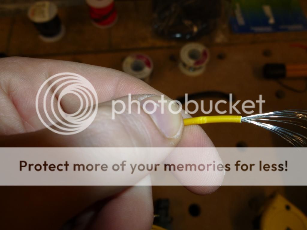
Another $5 tool from DX.com; this wire stripper works pretty well for the price. The first end stripped.
First of the lengths of wire cut, stripped, and twisted. Now just another seven of those to go.
Okay, all finished up with that. Now on to the extension I'll be... er... extending. Here's a simple trick for if you're ever doing a job like this: If you have to cut a multi-conductor cord and re-connect it, cut all the conductors at a different position in the harness. That way, you can match them up by length and not worry about getting them mixed up. (in this case it doesn't matter since we're only dealing with 12V and GND four times each, but this'll keep the pinout the same, even though it doesn't matter.) The other reason for doing this is that it keeps your splices from lining up right beside each other which both reduces the risk of a short, and keeps the bulk of the finished cable down - since your splices are likely going to be thicker than a single piece of insulated wire.

This extension clearly isn't using the highest quality wire insulation. You can see the grip marks made by the stripper on it. By contrast, the wire I'm splicing in had no such marks. If I wasn't going to cover the entire thing in heatshrink anyway, I wouldn't trust this around the metal edges of the case. Here's a couple pics:
BOO! The grip side of the stripper almost stripped the wire. That should never happen. Not the tool's fault, though. Bad wire insulation.
OKAY! On to the actual splicing. The method I'm going to use is a variation on what's known as a
Western Union or Lineman's splice.
(another link, if you're interested) They used this on telegraph wire where the lines were under mechanical stress; when done properly the splice is
stronger than the wire itself, and it conforms to NASA's requirements for use in space.
What I'll be doing is what I like to call a "Lazy Lineman's". Basically, a true lineman's splice needs to have at least a certain number of wraps, wrapped to a certain tightness, etc etc. Since I'm not intending to climb any buildings with the spliced wire, or put my life on the line by relying on it as a critical portion of a space vehichle, I'm not going to worry about the specifics or about certifying my splices, and just use the model; with the wire tightened by hand. It'll still be a lot stronger than the hook or lap method; last thing I want is a poor splice breaking inside a finished cable.
Here's the first splice ready to be soldered. (yes, I used red wire. Yes, red is the color code for +5V, yes this is a +12V circuit. It'll be covered in heatshrink. You'll never see it when it's done. Plus, red was the only color I had on hand beside black
")
)
And, there's one soldered. This connection is *never* coming apart. Now I just need to twist and solder another 15 splices.
Here's the first half of the extension done. You can see I got a bit too hot on a couple of those, and the insulation softened up enough that the clips on the helping hand dug in. OOPS! Ah well. Heatshrink will cover that and fix the weakness in the insulation.
Now that the first half is electrically connected, I'm going to slip a piece of heatshrink over each connection and shrink it on there to keep everything electrically isolated from one another.
And there's what it looks like done.
Once each connection is individually covered, I'm going to take some large diameter heatshrink and cover the exterior; kind of like sleeving the cable. This needs to be done before I make the last connections since I (at least, at the time I was doing this) didn't have a pin extractor to get the wires out of the connector and the heatshrink won't fit over the connectors. I took a piece to cover most of the length, shrunk it on, and cut another piece which will cover the remainder after I make the connections, and slipped it overtop, keeping it towards the finished side where the heat from my soldering iron won't cause it to shrink prematurely.
Next, I take the remaining end of the cable, and slip the individual pieces over their wires before making the electrical connection, for the same reason; I won't be able to do it after.
Solder those final eight connections, shrink their individual covering down, pull my sleeving over from the far side, shrink it down and there you go: One extended extension. Professional looking, solid, and the linesman's splices will likely outlast the connectors. Only thirty two stripped ends, sixteen wire splices, a ton of heatshrink, and a little solder later.
While I'm here, I'm going to extend a fan Y-cable. I'm using four fans (two on the 2x120mm rad and two on the 1x120mm rad in push-pull) and the ones on the single rad at the back of the case don't quite make it up to the fan controller in the Kama panel up front. I'll skip the detailed explanation, as I'm sure you get the idea by now. Using an old piece of Cat3 telephone wire pulled out of my dad's house. Waste not!
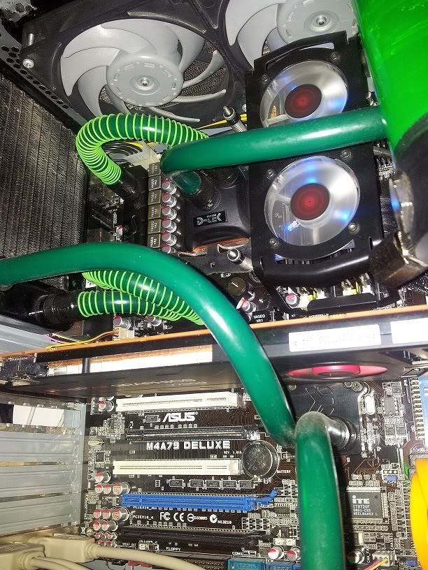
For SnGs, here we are back at the mock up. There's that proprietary pump connection I need to deal with...
Quick lighting test. Looks good.
Even with the EPS Pwr connected before the mobo's in place, and using a 45deg adaper on the rad, that connector just BARELY squeaked in there. Whew!
Another angle:
Oh, yeah. And I had to modify the backplate cutout since the CPU socket doesn't sit where the case apparently expects it to; thanks Antec. Maybe they intended it for a different board, or maybe for intel. At any rate, by this point I was long tired of taking the motherboard back out of the case to fit a heatsink.
Back from our detour. Pump connector.
Apparently, there's +12, GND, Tach, and PWM present here. Apparently, it's a proprietary form of PWM and won't respond to a standard PWM signal from your average motherboard. You can take
Martin's word on that. No matter. It runs fine at full blast on 12V, or you can use a fan controller as long as the controller is rated for at least 12W per channel. I elected to just solder in a molex and run the pumps at full.
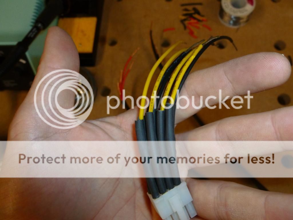
I cut each connector off, pre-flagging each wire's function.
Now that I've got the connector off, I'm going to sleeve the four wires together, to make it look a bit better and help hide them as they run up the bracket to the top of the case. Using heatshrink here too.
I'm not a huge fan of LED lighting in computers, so at this point I'm not intending to add any. Perhaps I'll add in a switched white LED or two so I can show it off, then shut them off for daily use. At any rate, if I ever add them, I'd better plan for them now or it'll look horrid with wires running all over the place. I'll add in some pairs from a section of Cat5e. The color coded pairs will make it trivial to tell which pair goes where, and to keep polarity straight. Again, recycled wire, and more than enough ampacity to run an LED or two.
I'm putting the heatshrink on in sections, and where I figure I might put an LED in the future, I end a section of heatshrink, add my twisted pair to the bundle, and keep heatshrinking after. It'll end up just like an automotive harness.
Here you can see how it comes out. Since I don't intend to put any lighting in at the current time, I'll just neatly tuck those pairs out of the way.
You can see the wires from the third pump joining the bundle, and running up to be hidden at the top of the case.
Now I'm at the end, and ready to solder the power connector on.
As you can see, I've kept each pump's wiring seperate. 12 pump wires with no color code would be a big problem at this point if I hadn't flagged their functions and grouped them for each pump.
I'll just leave this here.

Yes, I'm a bit of a tool. It's okay.
[yt]1jOk8dk-qaU[/yt]
Still keeping things seperated.
Getting ready to solder that molex on. My wires are grouped into three sets, and sleeved up as far as I can go.
Since I'm not doing anything with the twisted pairs at this time, I'll cable tie them and they'll hide away nicely at the top of the case.
Next, I'll get that molex connector ready.
An old Molex off some fan adapter or something. I dunno. Those wires are pretty shrimpy. Let's beef them up a bit.
These I *do* have a pin removal tool for. Your average molex 4-pin is large enough that you can do it with a sharp object and a little skill, pushing the retaining flaps down on each pin, but it's easy to damage the pins, and it takes a lot less time with the tool. Picked it up for a couple bucks from FrozenCPU. Highly recommended if you're doing any amount of this sort of thing.
You simply push the wire all the way forward (towards the connector), insert the pin removal tool, move it around a bit, and pull the wire back out.
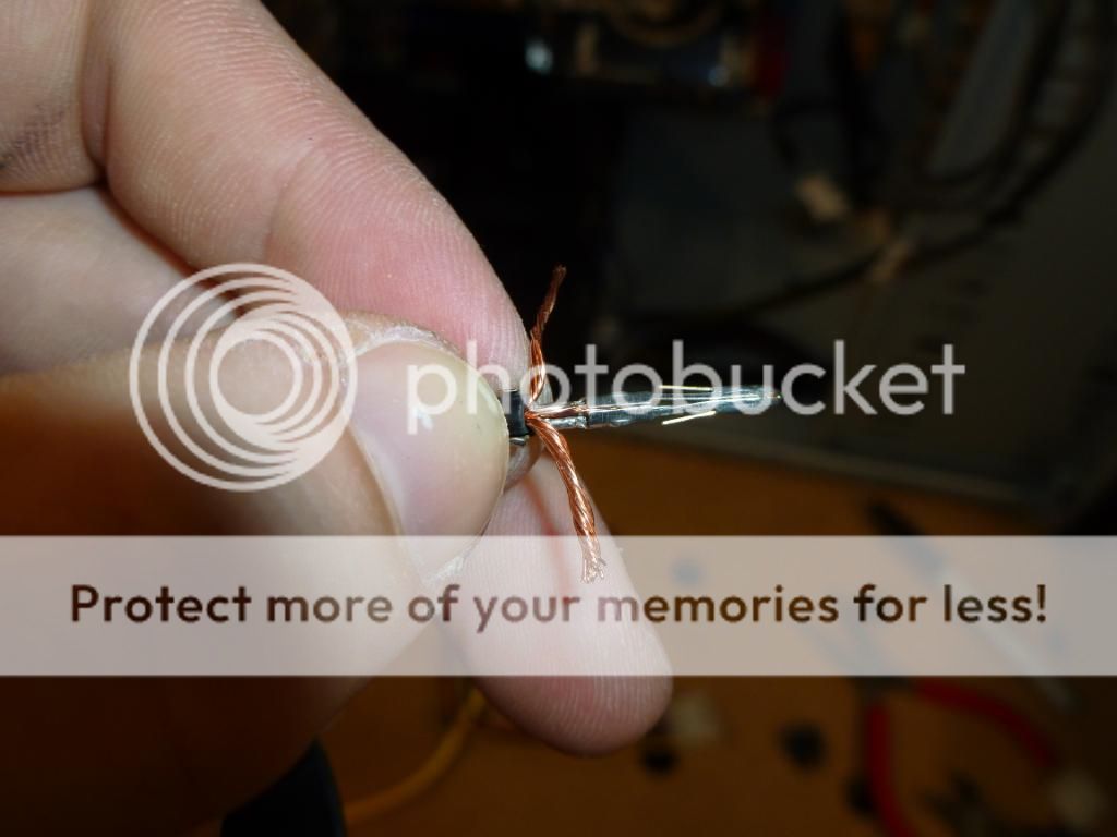
I'm going to be re-using these pins, so I carefully pried each flap open, and prepared some wire. My wire is oversized to this pin, so I had to get a little creative.
Once the wire's in place, I clamped the flaps back down, and wrapped the excess strands around the pin. Just enough room in the connector housing to fit.
Again, it's probably overkill, but I soldered them on too. I used the base of my iron tip-cleaner to hold the wire. For whatever reason, I was having a hard time getting the helping hand to hold it at the angle I needed.
Double-check that the retaining flaps are in good shape and in the right position, and insert into the connector housing. Again, the color code is wrong; it should be yellow, but I didn't have yellow. And again, nobody's going to see it or be working on it once it's in the PC. If I was building this for somebody else I would have made sure to use yellow wire.
Now we'll attach the three pumps' power wires to the respective wires on the molex. Still doing the lazy lineman's splice.
And now, a crappy video of me doing the last splice
wrong. I was using a cheap point n' shoot digital camera on a tripod, and I was mostly focusing on staying the heck out of the shot. So this one's not even a
lazy lineman's splice. It's something else. Again, doesn't matter. Still far stronger than a hook or lap splice. Not my best soldering technique either.
Side note: It's hard to solder with a camera in your face, and your arms wrapped around a tripod.

You can skip everything after 5minutes if you've read the project log (or the whole thing if you want

) since I'm just explaining.
Additionally
In the time since I last updated the project log, I've added one of these into the hardware specs.
Pretty happy with it so far. Computer boots up nice and quick, and there's enough room for one or two games I play often to be put on it, even if they're really big games.
WELL I guess that mini-update wasn't as mini as I thought it would be. That's okay, I have to make up for lost time here. Until next time


")


 Now, there's still not enough built up to sand the thing down and paint it without seeing everywhere the pieces come together (and now where the foam was eaten away at the raw edges). What the resin did do however, was stiffen the whole thing up quite a bit, and give me a decently strong base to work off of.


 also, some of these are pictures that were done with the crappy camera, sorry.


 The other problem? No threads on one of the thumbnuts that came with one of the GPU blocks, and there aren't any extra nuts in the package. (Here I'm pulling a tactical facepalm. One of the reviews I read about these blocks, same thing happened to the reviewer. His comment was even along the lines of "I'm sure this is just a pre-production issue, and even so EK could deal with it by just including an extra nut or two")


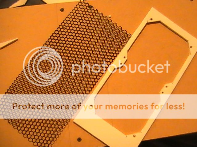
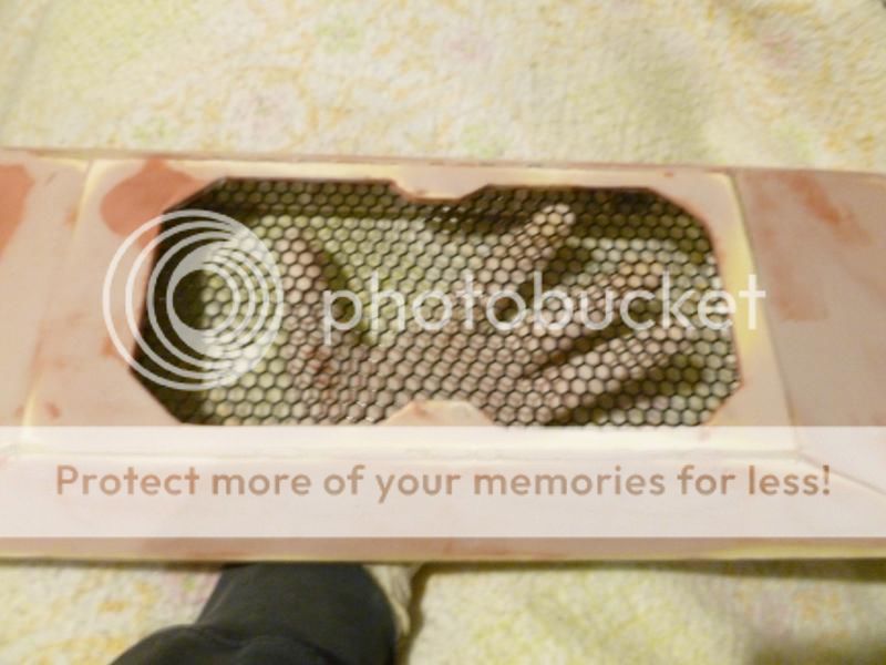
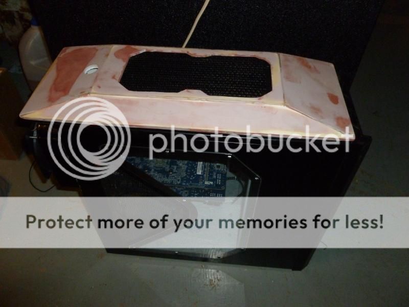
 Here's what I settled on: