• Welcome to TechPowerUp Forums, Guest! Please check out our forum guidelines for info related to our community.

POWER SUPPLY - PSU PWR CMD HELP!

seiiz001

New Member
Joined
Oct 10, 2020
Messages
4 (0.00/day)
Hello All!
I am in a pickle..

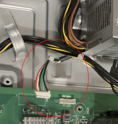
I have a 400W HP power supply with a 7 pin 6 wire connector going into the motherboard labeled "PWR CMD".
I changed my PC case for better airflow but I have a problem getting this wire to reach and connect into the motherboard because it is too short. I literally only need maybe 2-4 more inches on it.

My question is can i splice this wire to make it longer so that it will reach?
Can i use any type of wire with similar gauge? Perhaps some wire from a spare case fan as its similar gauge/thickness??

I looked online for awhile and i really have no other options, there are no adapters or extensions for this type of 7pin-6wire PSU->MOBO connector that i know of, and i am at a complete loss.
I can't change it out completely because it is hp proprietary, so the only thing i can come up with is to splice the wires to lengthen them the short amount that i need so that it can reach the MOBO and connect into it.

I have attached a picture of the connector and wire..

Any advice, suggestions, answers will be much appreciated, thank you !
 

Attachments

  • IMG_2871.png
    IMG_2871.png
    2.1 MB · Views: 4,816

sneekypeet

Retired Super Moderator
Joined
Apr 12, 2006
Messages
29,409 (4.47/day)
System Name EVA-01
Processor Intel i7 13700K
Motherboard Asus ROG Maximus Z690 HERO EVA Edition
Cooling ASUS ROG Ryujin III 360 with Noctua Industrial Fans
Memory PAtriot Viper Elite RGB 96GB @ 6000MHz.
Video Card(s) Asus ROG Strix GeForce RTX 3090 24GB OC EVA Edition
Storage Addlink S95 M.2 PCIe GEN 4x4 2TB
Display(s) Asus ROG SWIFT OLED PG42UQ
Case Thermaltake Core P3 TG
Audio Device(s) Realtek on board > Sony Receiver > Cerwin Vegas
Power Supply be quiet DARK POWER PRO 12 1500W
Mouse ROG STRIX Impact Electro Punk
Keyboard ROG STRIX Scope TKL Electro Punk
Software Windows 11
Joined
Sep 21, 2018
Messages
96 (0.05/day)
Location
Germany
Processor Ryzen 7 3700x
Motherboard AsRock X570M Pro4
Cooling Be Quiet Dark Rock Pro 3
Memory 4 x 16 GB Crucial Ballistix Sport LT red 3000C15 @ 3800C16 Micron rev E
Video Card(s) Zotac RTX 2070 mini
Storage Corsair MP510 1.92TB
Display(s) Samsung U32J592UQU 31.5" UHD + Fujitsu P19-2 19" 1280x1024
Case Jonsbo U3 mATX
Audio Device(s) ATH-M50
Power Supply Corsair SF600 600W SFX [currently RMAed]
Mouse Logitech G500
Keyboard QPAD MK-50 mechanical
Software Win10Edu_64
Hey!
I doubt the wire is carrying much load (amperage), so the wire gauge will not matter too much. That said, mixing wire gauges is not really a good idea, but you knew that already. To me, it looks like a JST connector with a PH/2.0 mm spacing. You could get the connector and wire up an adapter yourself or get something like this, maybe it is available in your country (aliexpress if you are patient): https://www.ebay.de/itm/JST-PH-2-0-mm-7-Pin-Stecker-und-Buchse-ca-30-cm-Kabel-/123295393677
You could measure it a bit yourself and find out if that connector is correct. I am kind of against wire splicing in anything that isn't meant to be a quick prototype or proof of concept. If something will run for a long time, I find it is a good idea to invest a little time into making it correct. But if that isn't your mind set or you cannot get those JST PH connectors, splicing wires should work. The higher grade the wire the better, but again, it doesn't seem to have a lot of load on it.
 

seiiz001

New Member
Joined
Oct 10, 2020
Messages
4 (0.00/day)
Hello, thank you both for the timely, in depth responses!!

So, it can be done if wire gauges are similar and splice/solder it good..?

I am honestly afraid and need reassurance because i was reading online that you can fry your motherboard or burn out your PSU..people saying to use multimeters to make sure the voltage matches ect. not sure if that is the same situation i am in but kinda got me worried.

Do you gentleman think this connector set would work, it is very similar(if not the same) to the one you sent me.
Even if i have to just use the wires from it and not the connectors to spice and solder all the wires together.


I read some things about voltage/watt loss if you extend these wires too much as it is main rail pc component and are very sensitive?
should i be concerned about that? I am kinda overlooking that because i only need to extend these wires a few inches longer.

 
Joined
Sep 21, 2018
Messages
96 (0.05/day)
Location
Germany
Processor Ryzen 7 3700x
Motherboard AsRock X570M Pro4
Cooling Be Quiet Dark Rock Pro 3
Memory 4 x 16 GB Crucial Ballistix Sport LT red 3000C15 @ 3800C16 Micron rev E
Video Card(s) Zotac RTX 2070 mini
Storage Corsair MP510 1.92TB
Display(s) Samsung U32J592UQU 31.5" UHD + Fujitsu P19-2 19" 1280x1024
Case Jonsbo U3 mATX
Audio Device(s) ATH-M50
Power Supply Corsair SF600 600W SFX [currently RMAed]
Mouse Logitech G500
Keyboard QPAD MK-50 mechanical
Software Win10Edu_64
For the set you linked: It is the same connector type I linked. "JST PH 2.0 mm" JST stands for Japans Solderless Terminals, PH stands for the spacing of the pins (2.0mm) and the power it supports. You can take out your favorite ruler and see if your connector has ~2.0mm space between each pin. If it does, you should be good. Otherwise take a look at this link and see if the other types match. JST is a very common connector in electronics and PCs and HP would not invest in a proprietary one, it costs too much.

And the voltage/watt loss: The cable you are "operating" on is not going to transfer a lot of power (amperage). It seems like a control type cable that communicates between motherboard and PSU and tells the PSU that the PC was powered on. There is not a lot of amperage going through those wires, so there will not be a lot of voltage drop or power/heat issues. If you were to extend the GPU cables (those 6 or 8 pin ones on high powered GPUs), that could be a different story and you should get a correctly made extension cable if possible.

And any time you play around with wires, you can damage stuff. You need to make sure that the job is done correctly, i.e. no bare metal shining through anywhere (that is where the heat shrink tubing comes into play from peet). And don't mix up the wires, but they are color coded, so you should be good there as well. Just don't mix up the 2 black wires, it could matter.
 

seiiz001

New Member
Joined
Oct 10, 2020
Messages
4 (0.00/day)
@ Deathy
Thank you for the help, and knowledge!!
I appreciate it! :respect:
When I get everything else squared away and done i will post pictures!
:clap:
 

seiiz001

New Member
Joined
Oct 10, 2020
Messages
4 (0.00/day)
@Deathy

I got everything in today and started work..
Those connectors were right on, exact fit and sizes and wires specs. I thank you very much for linking me those parts and for your expertise advice!
I wanted to just click them in to make it longer but on one end I’d have to pin the wires in to an actual connector or header? Unless I used two sets and spliced them together opposite the connector side.. At the end so it would have females on both side; Although I would only have to splice it in one place if I did that way.. maybe I should of done that.. too late now anyway

1 done 5 more to go!
I hope this is correct enough!

@sneekypeet
I ended up just stripping 1/2 inch or less off each end and making a Y with both wires and twisting as tight as I can and then folding alongside the wire. I’d like to have soldered it as you said, but I don’t have solder gun and no exp in doing
anyways. I am using a smaller diameter heat shrink tube and then a slightly larger diameter one to go over the actual splice where it is bigger and I think it came out great! I thank you for linking that set for helping me!!

All done! ✅
Works.. so far!
 

Attachments

  • DB8DFDEB-D5A0-4128-9717-DF69C5F5B7EA.jpeg
    DB8DFDEB-D5A0-4128-9717-DF69C5F5B7EA.jpeg
    2.7 MB · Views: 1,157
  • B266DCD9-7F1B-42C5-8656-04199BDC95E4.jpeg
    B266DCD9-7F1B-42C5-8656-04199BDC95E4.jpeg
    702.5 KB · Views: 991
  • AD7E2FC2-A3EA-4B7C-977E-20B6161BBC9F.jpeg
    AD7E2FC2-A3EA-4B7C-977E-20B6161BBC9F.jpeg
    682.3 KB · Views: 978
  • CD13A6F0-09D2-4CE7-8A43-811F83833948.jpeg
    CD13A6F0-09D2-4CE7-8A43-811F83833948.jpeg
    1.4 MB · Views: 1,582
  • 1507A2E6-B742-4337-86A0-9307B9864C5F.jpeg
    1507A2E6-B742-4337-86A0-9307B9864C5F.jpeg
    1.7 MB · Views: 991
  • 1776B4B6-677A-4CAF-9E0C-37319F0CC8EF.jpeg
    1776B4B6-677A-4CAF-9E0C-37319F0CC8EF.jpeg
    983.7 KB · Views: 979
  • A013468B-806B-4E59-90F3-462CA95A3D77.jpeg
    A013468B-806B-4E59-90F3-462CA95A3D77.jpeg
    1 MB · Views: 1,130
  • FD19D737-DBF7-4000-9581-3A562D6183E8.jpeg
    FD19D737-DBF7-4000-9581-3A562D6183E8.jpeg
    1.9 MB · Views: 1,752
  • DAE3B074-5880-431F-BA3F-ABAE22B87E7B.jpeg
    DAE3B074-5880-431F-BA3F-ABAE22B87E7B.jpeg
    1.1 MB · Views: 1,874
Top