Doing the thermal calculation is hard; but thermodynamics is hard.
If you want to be totally accurate with your calculation, you have to instrument each layer of material in your stack.
So: CPU die, liquid metal, copper shim, liquid metal, layer of nickel on HS, HS thermal spreader, fins or water (or LN2) temperature, ambient air.
Every layer comes into the equation.
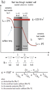
If you do w/m/ degree K on each material, you can make it all come out reasonably easy.
Thickness in meters is easy, degrees k is easy; Watts is not because of the varying area the thermal flux is passing thru is not constant, and it's not evenly spread across the entire area of a layer either.
Measuring it all at various loads with thermocouples and a NI card, and dumping it into Excel is pretty easy.
If you treat the stackup of thermal resistances as a series electrical circuit with the thermal difference of the CPU die to ambient as the overall Thermal driver, you can see where in the stack the highest thermal gradient is, and that's your limiting material.
Get rid of it and try again, until you can't get rid of anything else.
")
If the biggest gradient is the cooling fin or water to ambient, you need more fin, more radiator, or more cowbell.

I have to say; the only real reason we do this whole execrcise is the more cowbell thing; I consider myself ripping off intel or AMD when I manage a real OC over the "advertised" clocks.
Fuck those assholes, that want to charge us Serious precious dollars for meager incremental gains.
I'll wait a few years, and rock my x58 system with a previously $3k processor, you bastards.
Now I'm rockng my x97 system the same way.