 66
66
ASUS Maximus III Gene P55 Review
The Board - A Closer Look »The Board - Layout
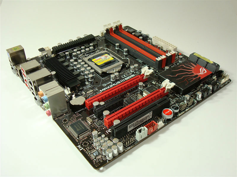
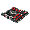
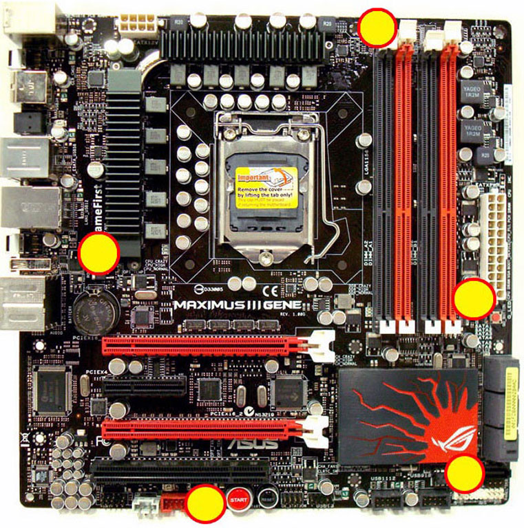
With the board out of the box, the red/black/white colour-scheme stands out tall and proud. Everything seems really well placed, and both the 24-pin and 8-pin connector sit in their standard spots at the edge of the board.


Here are the front and the back of the board, high-res versions are also available (front, back). If you choose to use these images for voltmods etc, please include a link back to this site or let us post your article.

The board features two physical x16 PCI-E connectors, but with a graphics card in both of them, they are each electrically x8. In between them sits a x4 PCI-E slot, and below all three is a single PCI slot. Such thought was given to the layout that even with two full-length video cards installed, all the buttons and LEDs are easily accessible.

The backplane itself has a large assortment of connectors. We find eight USB 2.0 ports, and one other USB port swapped 90 degrees for the ROG Connect feature. One FireWire port, one Gigabit Ethernet port, as well as SPDIF and analog audio outputs are located here as well. A clear CMOS button which allows you to clear the CMOS without opening the PC chassis, eSATA connector, and the ROG-enable button fill out the rest of the I/O, with a single PS/2 connector on the top left. This PS/2 connector does not support mice, but is included for those that use PS/2 keyboards, a great feature for those concerned with n-rollover.

Looking at the CPU socket, we can see all ten phases for CPU power; eight for the CPU itself, and two for the CPU's internal northbridge. The MOSFETs that provide the chokes with power are hidden neatly under the black heatsinks you see, which have a heatpipe connecting between them to help eliminate hotspots around the processor socket.
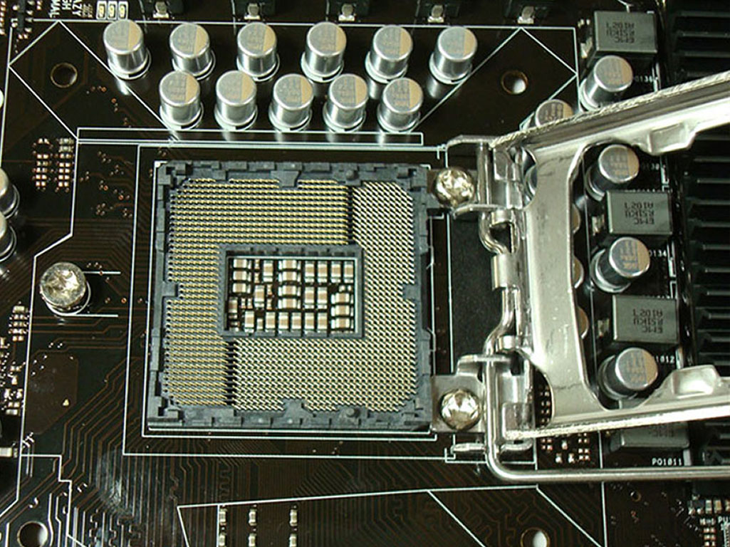
Lifting the socket bracket and removing the protective cover, we can see that there are no missing components in the socket, ensuring smooth power delivery to the processor. All surrounding components are short in stature, including the PWM heatsink, ensuring maximum compatibility with aftermarket CPU cooling solutions.

Flipping the board over, we can see a capacitor attached for each CPU phase, but not for the northbridge phases. Those installing an aftermarket cooling solution need to make sure not to damage these parts when using an aftermarket backplate. I encountered no issues when installing a Corsair H50 watercooling system, and even the protruding pins from the front-side capacitors met no interference from the backplate, so some attention has been given to deciding on their location on the board.
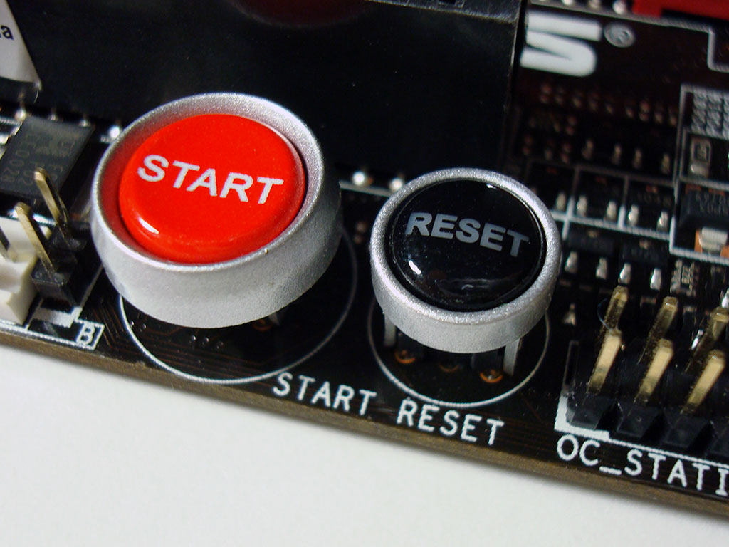
As is standard on all ROG-branded motherboards, a POWER and RESET button are included on-board, and left of them we can see one of the two 4-pin PWM fan connectors, which include a connection for a thermal diode which can then be used to regulate fan speed according to temperature. The other header like this is between the back I/O and the CPU MOSFETs.

ASUS's layout is clean and clear - Even the pin headers are all nicely aligned with the board edge, making it easy to both connect, and keep wires tidy. The BIOS chip is also located here at the board edge, should you need to access it for any reason, along with another fan header.
ASUS has included a full compliment of fan headers for case fans, all five of which are PWM controlled. Three of them (CPU and CHASSIS x2) can be set to run full speed, or set to vary the fan speed using the Q-FAN function, with the two "OPTION" fan headers offering connectors for thermal diodes which can then control the fan speed based on temperatures reported by the probes. Unfortunately, there were no probes included with the board. The two "OPTION" fans can also be set to a duty mode which offers settings from 40%-90%, increasing by 10% at a time. The Q-FAN option allows for three dynamic profiles which vary the fanspeed according to system load and temperatures.

Just above the SATA headers is a little red button labeled “GO_BUTTON”, and peeking out from the southbridge heatsink is a little chip labelled “ROG”. An LED to indicate HDD activity is also here, hidden right next to the SATA ports.

To the right of the socket, we find the four DDR3 DIMM slots, the 24-pin ATX power connector, and the 2-phase power section for the memory. The DIMM slots feature ASUS's new DIMM connector that only has clips on one side of the slot. Given the close proximity of the primary PCI-E slot, their usefulness is clearly understood. However, this design choice may affect those with memory coolers that use clips to attach to the memory slots.

The southbridge heatsink is quite large, although underneath the red sun logo is nothing other than open air, and a red LED to illuminate it. This very bright light will pulse from on to off slowly, and can be disabled from within the BIOS. While one might question having a red-hot sun on your motherboard, it's visual effect definitely adds to the board's presentation.
Apr 23rd, 2024 20:25 EDT
change timezone
Latest GPU Drivers
New Forum Posts
- Sexy Mechanical Keyboard Thread (484)
- What's your latest tech purchase? (20318)
- The TPU UK Clubhouse (24766)
- need help with motherboard/ ram compability certainty (14)
- My computer setup - Request for opinions (12)
- Show us your collections thread!! (282)
- Realtek Modded Audio Driver for Windows 10/11 - Only for HDAUDIO (5687)
- What phone you use as your daily driver? And, a discussion of them. (1454)
- Is there a technical reason that Windows 11 doesn't have built into it battery charge limitation? (37)
- ThrottleStop 9.6 Voltage won't change (1)
Popular Reviews
- Fractal Design Terra Review
- Corsair 2000D Airflow Review
- Thermalright Phantom Spirit 120 EVO Review
- Minisforum EliteMini UM780 XTX (AMD Ryzen 7 7840HS) Review
- ASUS GeForce RTX 4090 STRIX OC Review
- NVIDIA GeForce RTX 4090 Founders Edition Review - Impressive Performance
- ASUS GeForce RTX 4090 Matrix Platinum Review - The RTX 4090 Ti
- MSI GeForce RTX 4090 Gaming X Trio Review
- MSI GeForce RTX 4090 Suprim X Review
- Gigabyte GeForce RTX 4090 Gaming OC Review
Controversial News Posts
- Sony PlayStation 5 Pro Specifications Confirmed, Console Arrives Before Holidays (116)
- NVIDIA Points Intel Raptor Lake CPU Users to Get Help from Intel Amid System Instability Issues (106)
- AMD "Strix Halo" Zen 5 Mobile Processor Pictured: Chiplet-based, Uses 256-bit LPDDR5X (101)
- US Government Wants Nuclear Plants to Offload AI Data Center Expansion (98)
- Windows 10 Security Updates to Cost $61 After 2025, $427 by 2028 (84)
- Developers of Outpost Infinity Siege Recommend Underclocking i9-13900K and i9-14900K for Stability on Machines with RTX 4090 (84)
- TechPowerUp Hiring: Reviewers Wanted for Motherboards, Laptops, Gaming Handhelds and Prebuilt Desktops (74)
- Intel Realizes the Only Way to Save x86 is to Democratize it, Reopens x86 IP Licensing (70)