 36
36
ABIT AT8 Review
Layout continued »Board Layout


Click here for a 3000x2500 high-res shot of the board (3 MB download), the backside is here.

Lots of space near the CPU area. There shouldn't be any space issues with huge CPU coolers because the chipset heatsink is low-height.

The big hole in the middle is supposed to improve airflow to the heatsink which is connected to the chipset via heatpipe. The other connectors are pretty standard. From left to right PS/2 mouse, PS/2 keyboard, Optical Audio, 3.5mm Audio jacks, four USB ports, Firewire and Gigabit Ethernet.

The manual will tell you, that you have to put the modules right next to each other for Dual-Channel. A configuration with more space in between would have been better for memory temperatures.
Connectors

The 24-pin ATX power connector is very conveniently placed near the edge of the motherboard. An extra 5.25" power connector is available near one of the PCI-E slots to supply additional power to the video card. This might be needed for optimum stability when running in CrossFire mode. I don't like the placement of the ATX12V connector, near the ATX power connector would have been better. On the other hand, having the connector near the CPU power conversion circuitry sure improves power stability.
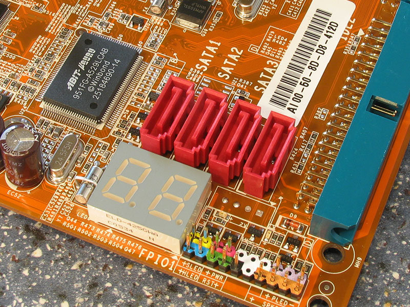
The ULI chipset has four SATA-II ports. A helpful feature when debugging boot problems is the POST code indicator. During startup it will go through a sequence of numbers. If your system crashes you can find out during which step it happened. For example POST code C1 is memory initialization.

ABIT has been using angled IDE connectors for quite some time. They help reduce the cable mess near the motherboard.

The front panel header's color coding make it easy to identify where your cables have to go. I miss the push buttons for Reset and Power which were available on previous ABIT motherboards.

A total of six fan headers are spread around the board. All of them are speed-monitored by the UGuru chip.
Slots


The most important feature of this board is support for CrossFire. When you are using only one video card it has to be installed in the bottom PCI-E x16 port with the orange shadow card in the other one. It is also possible to force a certain configuration via the BIOS settings. When running in Crossfire mode each PCI-E video card port will run at x8.
Apr 25th, 2024 08:58 EDT
change timezone
Latest GPU Drivers
New Forum Posts
- i7-12800HX Overheating Issues (1)
- (Anti) SFF fun house (354)
- What's your latest tech purchase? (20339)
- Intel ARC Firmware Compilation Matrix (22)
- Alphacool CORE 1 CPU block - bulging with danger of splitting? (6)
- Bizarre Throttlestop issue (6)
- Core i5-6300U (17)
- Last game you purchased? (255)
- Share your AIDA 64 cache and memory benchmark here (2916)
- What phone you use as your daily driver? And, a discussion of them. (1472)
Popular Reviews
- Fractal Design Terra Review
- Thermalright Phantom Spirit 120 EVO Review
- Corsair 2000D Airflow Review
- Minisforum EliteMini UM780 XTX (AMD Ryzen 7 7840HS) Review
- ASUS GeForce RTX 4090 STRIX OC Review
- NVIDIA GeForce RTX 4090 Founders Edition Review - Impressive Performance
- ASUS GeForce RTX 4090 Matrix Platinum Review - The RTX 4090 Ti
- MSI GeForce RTX 4090 Suprim X Review
- MSI GeForce RTX 4090 Gaming X Trio Review
- Gigabyte GeForce RTX 4090 Gaming OC Review
Controversial News Posts
- Sony PlayStation 5 Pro Specifications Confirmed, Console Arrives Before Holidays (116)
- NVIDIA Points Intel Raptor Lake CPU Users to Get Help from Intel Amid System Instability Issues (106)
- AMD "Strix Halo" Zen 5 Mobile Processor Pictured: Chiplet-based, Uses 256-bit LPDDR5X (101)
- US Government Wants Nuclear Plants to Offload AI Data Center Expansion (98)
- Windows 11 Now Officially Adware as Microsoft Embeds Ads in the Start Menu (87)
- Developers of Outpost Infinity Siege Recommend Underclocking i9-13900K and i9-14900K for Stability on Machines with RTX 4090 (85)
- Windows 10 Security Updates to Cost $61 After 2025, $427 by 2028 (84)
- AMD's RDNA 4 GPUs Could Stick with 18 Gbps GDDR6 Memory (81)