 3
3
Corsair CS Series Modular 650 W Review
Voltage Regulation, Hold-up Time & Inrush Current »A Look Inside & Component Analysis
Before reading this page, we strongly suggest a look at this article, which will help you understand the internal components of a PSU much better. Our main tool for the disassembly of the PSU is a Thermaltronics TMT-9000S soldering and rework station. It is of extreme quality and is equipped with a matching de-soldering gun. With such equipment in hand, breaking apart every PSU is like a walk in the park!

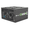
This unit is made by an OEM we had quite some time to study, Great Wall. The last PSU from Great Wall was pretty good, so our expectations are high. The small PCB of the CS650M uses a modern design and an LLC resonant converter is utilized in the primary side. We also come across a synchronous design with DC-DC converters for the generation of the minor rails in the secondary side. This is truly a Gold certified PSU since it is based on a highly efficient platform, not just an upgraded Bronze or Silver one.

A small PCB located right behind the AC receptacle hosts one X and two Y caps. We find the transient filtering components on the main PCB: These include two CM chokes, a single X cap and a pair of Y caps. We unfortunately didn't find an MOV (Metal Oxide Varistor), the small component protecting PSUs from surges off the mains grid. We also spotted an NTC thermistor, which protects the unit against large inrush currents, and a relay that bypass it once its job is finished.


The bridge rectifiers, two T15KB60, are installed on the primary heatsink.


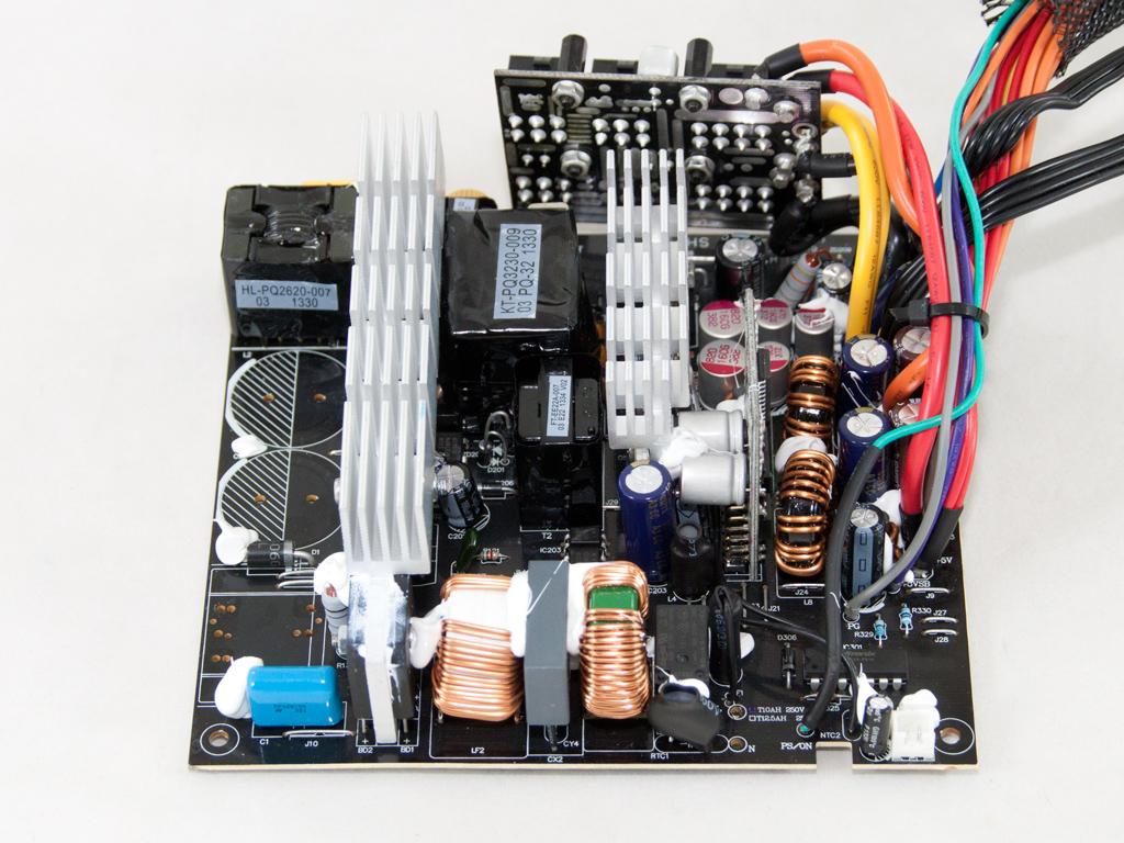
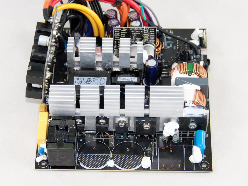
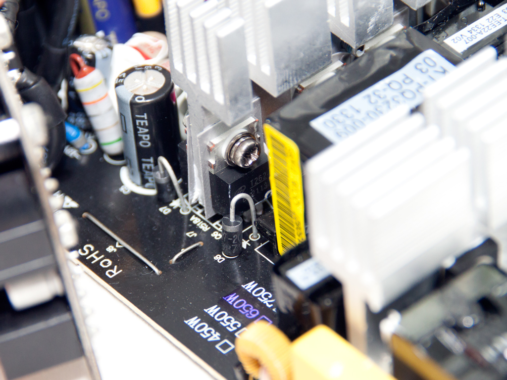
Two G30N60E fets and a BYC15-600 boost diode are used in the APFC, and a pair of Chemi-Cons (400 V, 270 µF each or 540 µF each, 85°C, SMQ series) act as bulk caps. As you can see from the last of the above photos, we had to remove the APFC inductor to provide you with a better view.
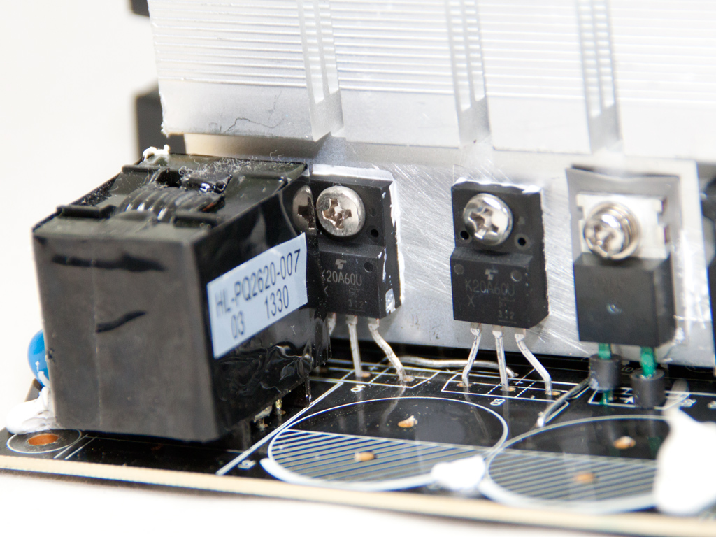
Two K20A60U fets act as main switchers.
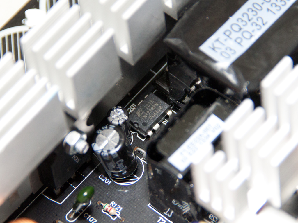
The standby PWM controller is a TNY278PN IC.


Four BV2113 fets in the secondary side regulate the +12V rail, and the minor rails are generated by two DC-DC converters housed on the same PCB. The combo PWM controller of the DC-DC converters is an APW7159, and each of them uses a pair of Infineon 040N03L fets.

The 5VSB rail is regulated by a single PFR20L45CT SBR.

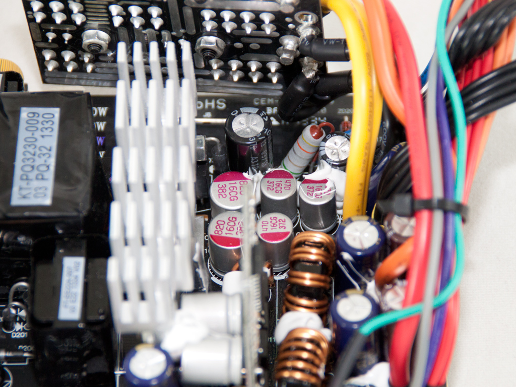
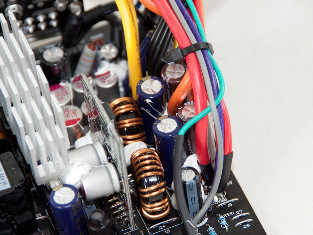

The secondary side uses a mix of polymer and electrolytic caps for ripple filtering. All polymer and most of the electrolytics, except two Elite ones, are provided by Teapo.

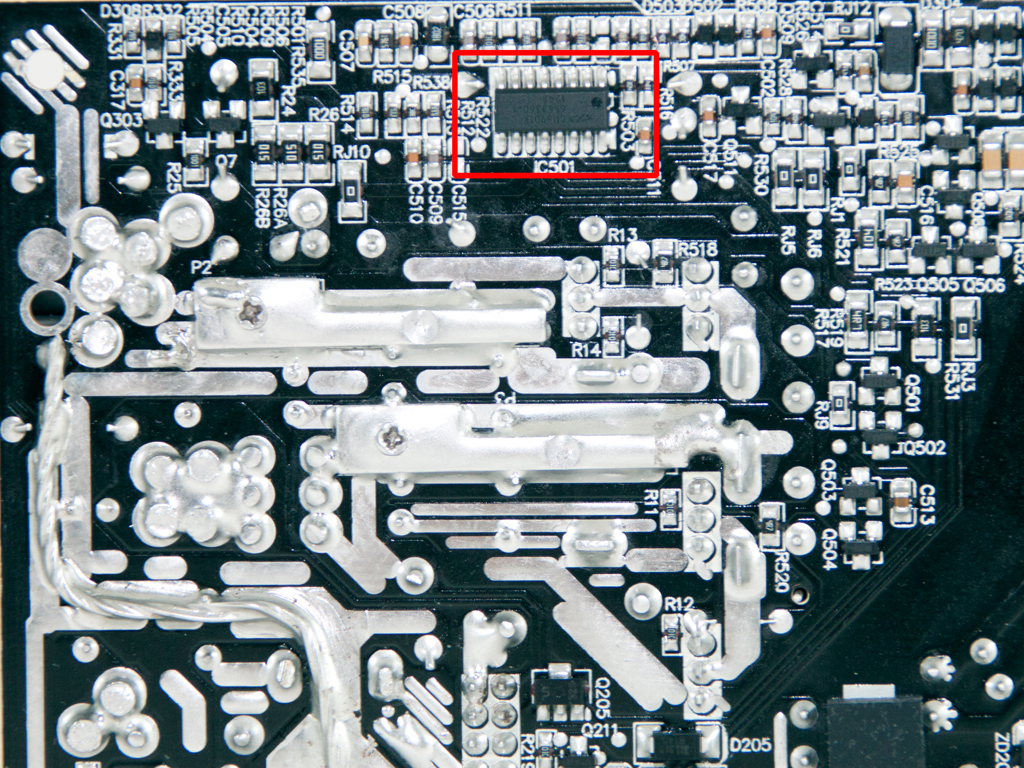
The supervisor IC, a Sytronix ST9S429-PQ14, is soldered to the component side of the main PCB. This IC is a rebadged Unisonic Technologies S3515 without OTP (Over Temperature Protection) support, so OTP must, if present, be implemented via another way. However, we only found one thermistor attached to the secondary heatsink, so chances are that OTP isn't provided irregardless of the unit's specs on paper. (Update: Corsair informed us that OTP is indeed present and it is implemented via the fan controller. In case the internal temperature reaches very high levels, it triggers one of the other protections of the supervisor IC, effectively shutting the PSU down)

The small modular PCB houses three polymer caps, two from CapXon and one from Elite.
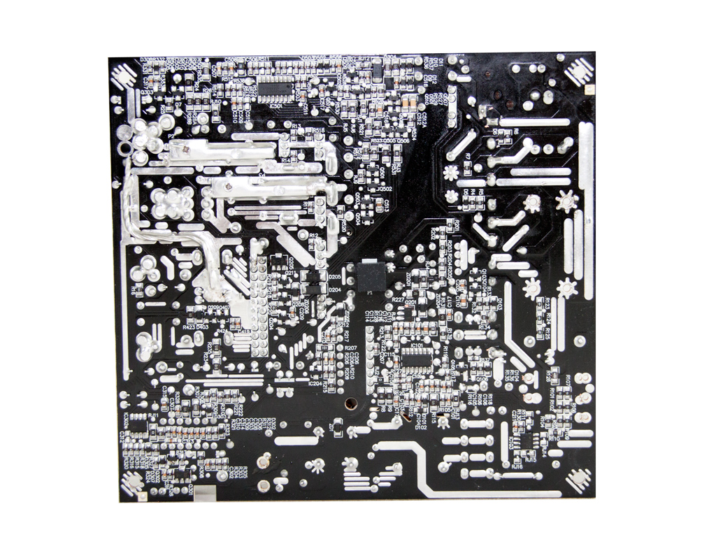


Soldering quality definitely isn't top, but you can't call it bad or even average. The PCB's primary side holds the PFC controller, a CM6500, and the LLC resonant controller, a CM6901 IC.


The cooling fan is provided by Hong Hua, and its model number is HA1225L12S-Z (120 mm, 12 V, 0.33 A, 1500 RPM). It is a medium-speed fan and produces very little noise while operating normally because of its very relaxed fan profile.
Apr 24th, 2024 09:09 EDT
change timezone
Latest GPU Drivers
New Forum Posts
- Official Board Game Discussion (16)
- EK seems to be having major issues (33)
- What phone you use as your daily driver? And, a discussion of them. (1464)
- What's your latest tech purchase? (20333)
- My computer setup - Request for opinions (15)
- Is It The 1080 TI The Best GPU Ever? (205)
- Wanted to get the drift what your opinion is on this topic (0)
- Looking to build another system (0)
- Core i5-6300U (10)
- Which one to choose from these 3 laptops offer? (21)
Popular Reviews
- Fractal Design Terra Review
- Corsair 2000D Airflow Review
- Thermalright Phantom Spirit 120 EVO Review
- Minisforum EliteMini UM780 XTX (AMD Ryzen 7 7840HS) Review
- ASUS GeForce RTX 4090 STRIX OC Review
- NVIDIA GeForce RTX 4090 Founders Edition Review - Impressive Performance
- ASUS GeForce RTX 4090 Matrix Platinum Review - The RTX 4090 Ti
- MSI GeForce RTX 4090 Gaming X Trio Review
- MSI GeForce RTX 4090 Suprim X Review
- Gigabyte GeForce RTX 4090 Gaming OC Review
Controversial News Posts
- Sony PlayStation 5 Pro Specifications Confirmed, Console Arrives Before Holidays (116)
- NVIDIA Points Intel Raptor Lake CPU Users to Get Help from Intel Amid System Instability Issues (106)
- AMD "Strix Halo" Zen 5 Mobile Processor Pictured: Chiplet-based, Uses 256-bit LPDDR5X (101)
- US Government Wants Nuclear Plants to Offload AI Data Center Expansion (98)
- Windows 10 Security Updates to Cost $61 After 2025, $427 by 2028 (84)
- Developers of Outpost Infinity Siege Recommend Underclocking i9-13900K and i9-14900K for Stability on Machines with RTX 4090 (84)
- TechPowerUp Hiring: Reviewers Wanted for Motherboards, Laptops, Gaming Handhelds and Prebuilt Desktops (78)
- Intel Realizes the Only Way to Save x86 is to Democratize it, Reopens x86 IP Licensing (70)