 5
5
EVGA SuperNOVA P2 1200 W Review
Voltage Regulation, Hold-up Time & Inrush Current »A Look Inside & Component Analysis
Before reading this page, we strongly suggest a look at this article, which will help you understand the internal components of a PSU much better. Our main tool for the disassembly of the PSU is a Thermaltronics TMT-9000S soldering and rework station. It is of extreme quality and is equipped with a matching de-soldering gun. With such equipment in hand, breaking apart every PSU is like a walk in the park!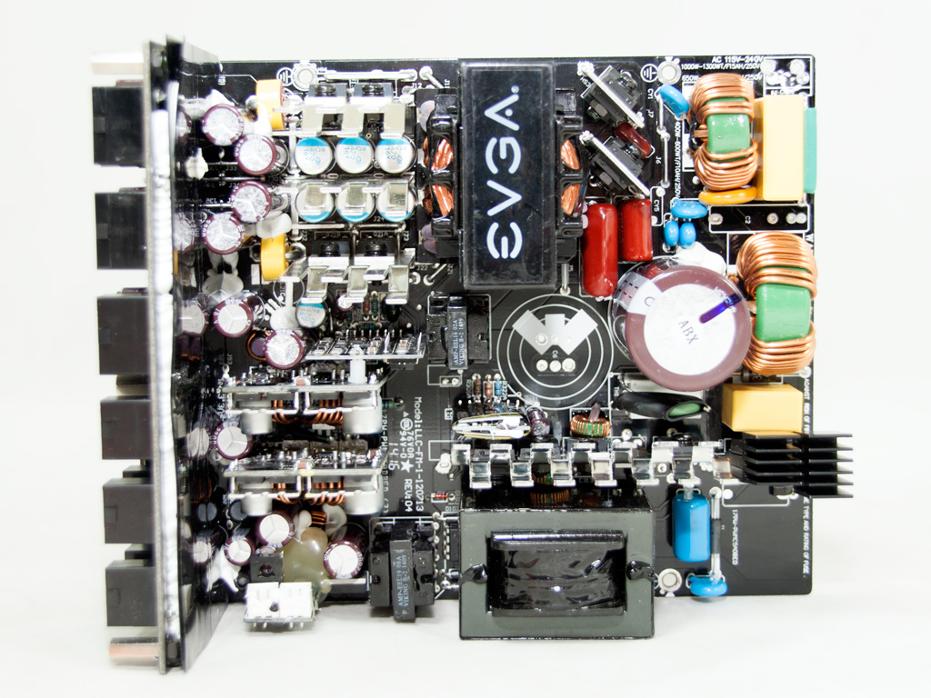


This PSU's OEM is Super Flower, and the same platform was used in the Leadex Platinum 1200 W, which we already reviewed. The primary side uses a full bridge topology and an LLC converter for boosted efficiency, while the secondary side exploits a synchronous design for the rectification of the +12V rail and two DC-DC converters for the minor rails.
The transient filter starts right at the AC receptacle. The first stage consists of a single X cap. The second part of the transient filter, located on the main PCB, consists of two CM chokes, two X caps, two pairs of Y caps, and an MOV. We also found a Transient Voltage Suppression (TVS) diode for additional protection against spikes.


Two parallel bridge Shindengen US30K80Rs) rectifiers are used.


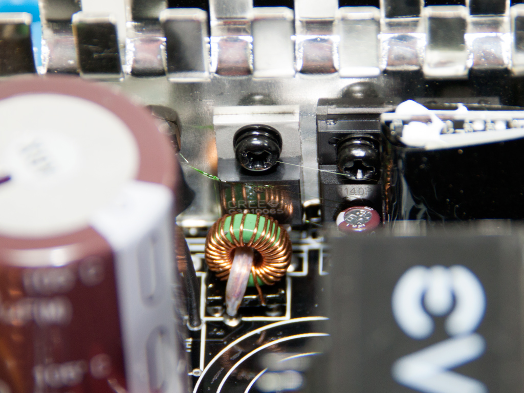


The APFC consists of three Infineon IPP50R140CP fets and two C3D10065A boost diodes—the second diode is bolted to the opposite side of the heatsink. Both parallel hold-up caps, provided by Nippon Chemi-Con (400 V, 560 μF each or 1120 μF combined, 105°C, KMQ series), are right in front of the transient filter, and while their combined capacity should cover the needs of this unit, the hold-up test proved otherwise.
An NTC thermistor protects the unit against large inrush currents, and an electromagnetic relay isolates it from the circuit once the start-up phase finishes.
This small and sealed PCB houses the APFC controller, an NCP1653A IC.

The standby PWM controller is an ICE3B0565 IC.


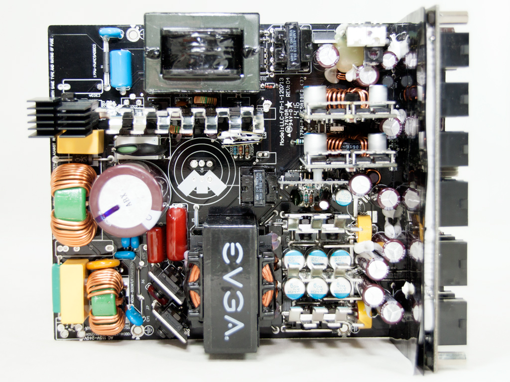
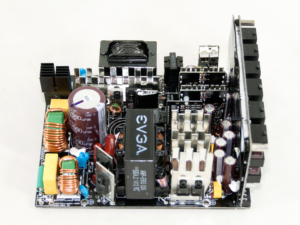
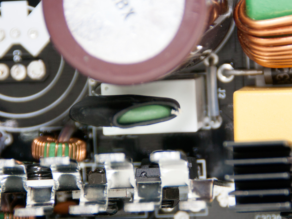
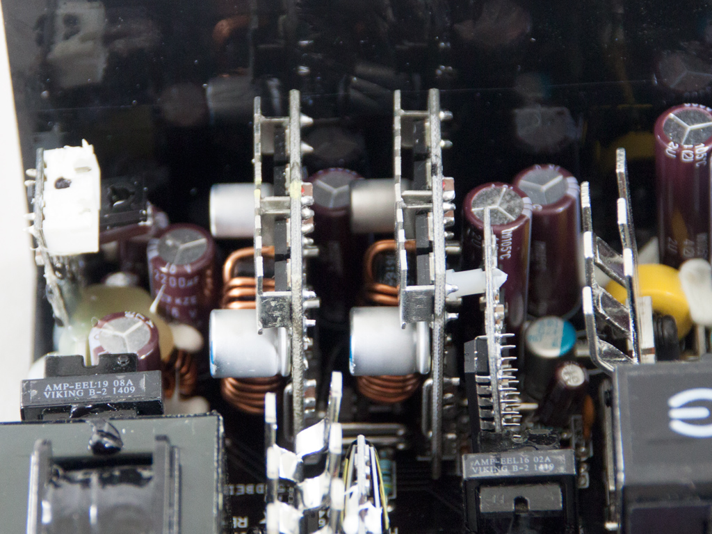
Four Infineon IPP50R140CP fets are used as main switchers. They are bolted to two small diagonal heatsinks because they don't need much cooling as the LLC resonant converter allows for loss-less switching.

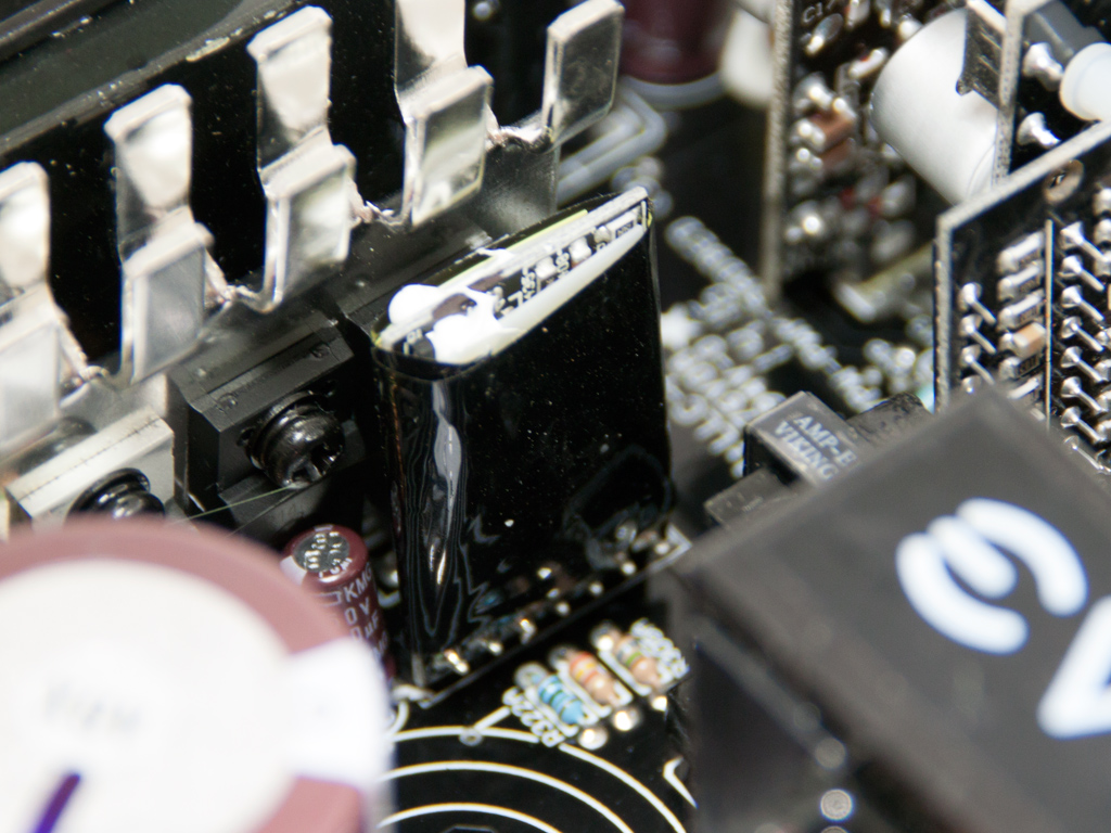
The proprietary LLC resonant controller is installed on this vertical daughter-board. Unfortunately, its marking, AA9013, don't reveal much, but it looks similar to the SF29601 IC Super Flower used in their previous-generation Platinum models.
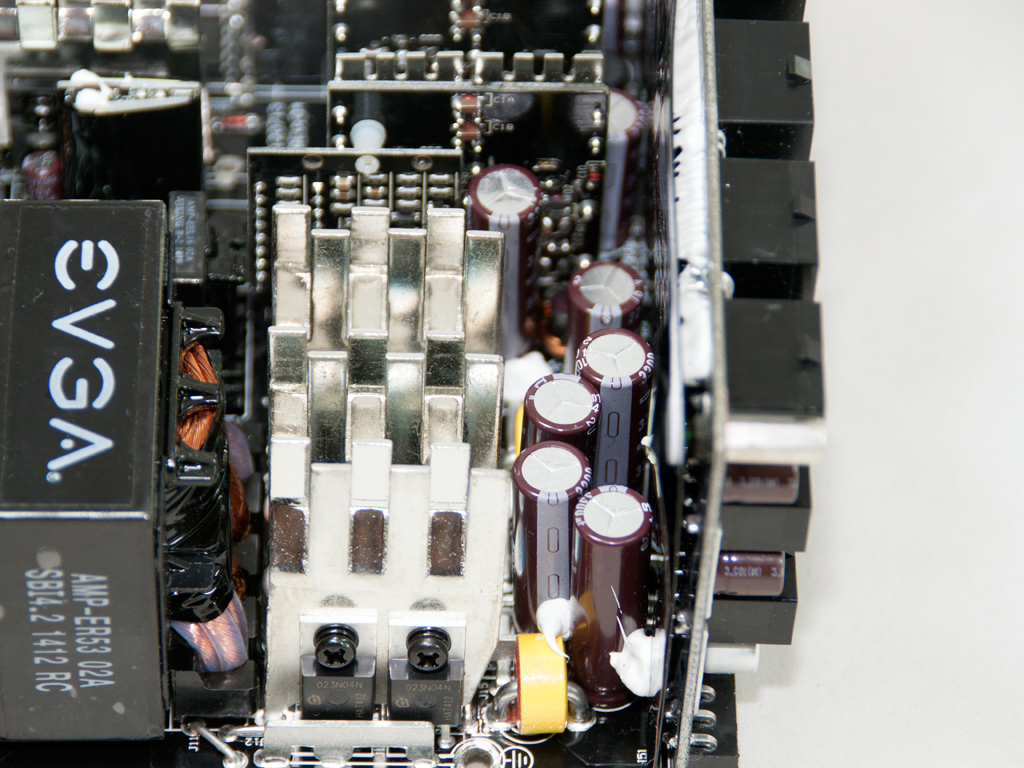


In the secondary side are three small, vertical heatsinks. The middle heatsink is empty, but the other two host eight fets in total (8x Infineon IPP023N04N). Six polymer Chemi-Con caps reside between these heatsinks, and a little further on are several electrolytic caps (rated at 105°C) by the same company. All are used to filter the +12V rail.

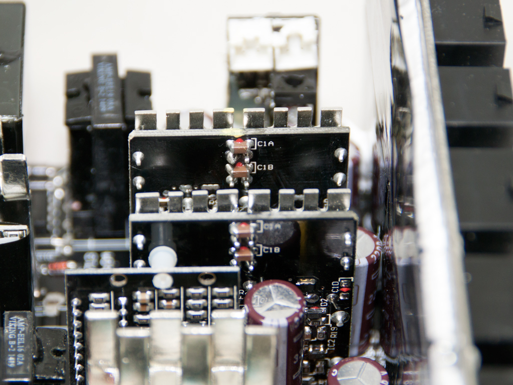
Both DC-DC converters responsible for the generation of the minor rails are covered by metallic shields for EMI protection.
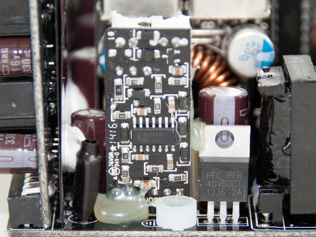
The 5VSB rail is rectified by a PFR40V60CT SBR (Schottky Barrier Rectifier). The fan-control board is right next to it, and on it is an LM324ADC. If you want to remove the fan header and the corresponding fan-control switch, you should be extremely careful while doing so because this small PCB is only held in place by the solder joints on its base, which can easily break and are really hard to fix. We applied lots of glue near the base to secure it properly.


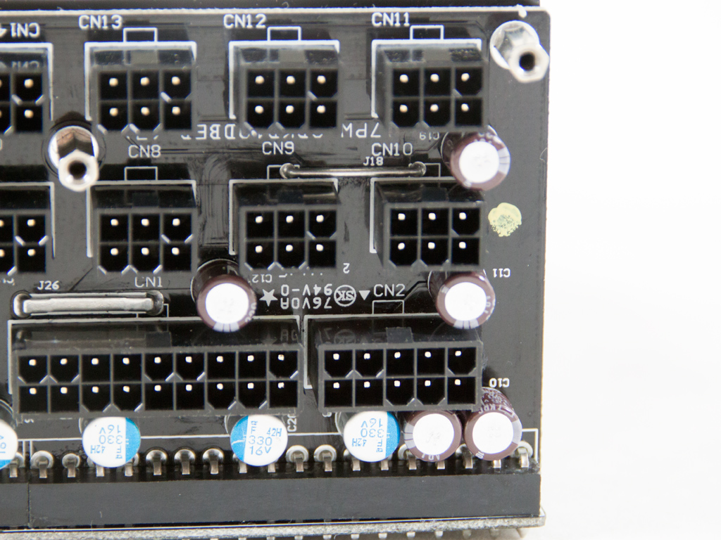
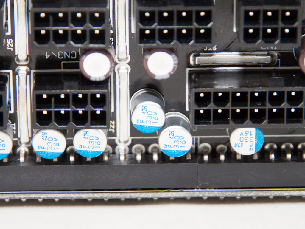
Many polymer and electrolytic caps on the modular PCB's primary side provide further ripple filtering. This is why SF's implementations are ripple proof.

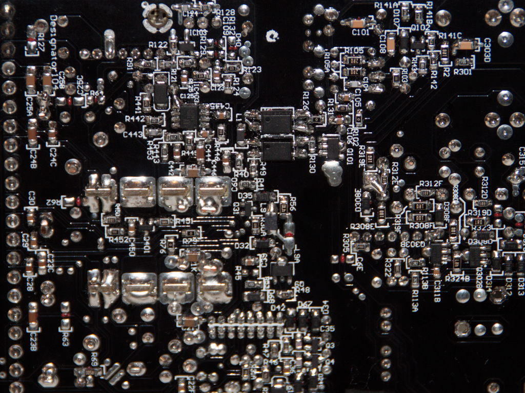


Soldering quality is fairly good. Not the best we have ever seen, it, judging by the unit's high performance, does the job pretty well.
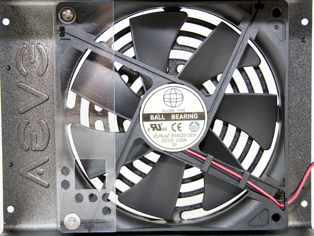
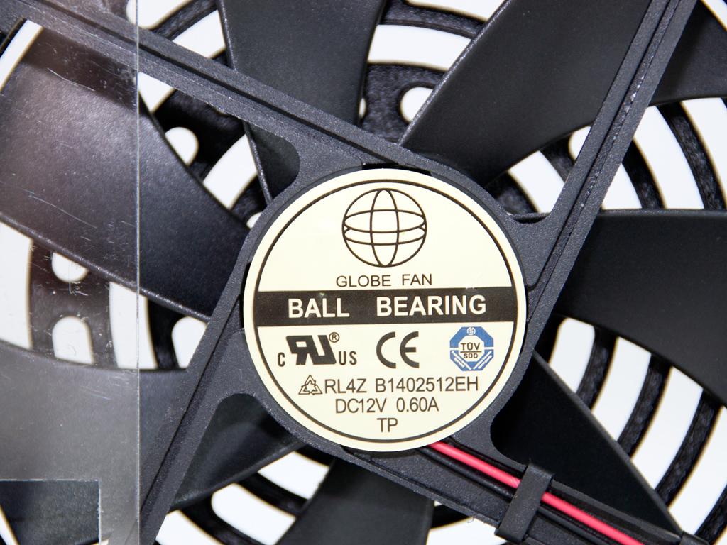
The cooling fan is by Globe Fan, and its model number is RL4Z-B1402512EH (140 mm, 12 V, 0.6 A, 2000 RPM, 153.47 CFM, 39.5 dBA, 70.000 MTBF). It is equipped with double ball-bearings and is rated for 0.6 A at 12 V, so it is quite strong and noisy at full speed. This unit's fan-control circuit thankfully runs the fan at much lower speeds most of the time. It will also not engage very often if you pick the semi-passive mode option and operate the unit normally.
Apr 19th, 2024 15:30 EDT
change timezone
Latest GPU Drivers
New Forum Posts
- Will a RTX 4070 TI super bottleneck a Ryzen 9 7950X3D? (39)
- [WIN11] 5700x3d Security processor Attestation: Not supported? (3)
- Is it possible to use Linux without the Terminal/command line? (27)
- Linus watercools (45)
- Which air cooler for a ryzen 9 5900x (160)
- Which terminal emulator do you use the most? (9)
- I9 13890HX undervolting Suggestions (2)
- Whats your favourite Linux Distro? (52)
- DDR5 RAM Speeds and the future (50)
- What can be changed in a VBIOS file? (PCI vendor etc) (4)
Popular Reviews
- Horizon Forbidden West Performance Benchmark Review - 30 GPUs Tested
- PowerColor Radeon RX 7900 GRE Hellhound Review
- Fractal Design Terra Review
- Corsair 2000D Airflow Review
- Thermalright Phantom Spirit 120 EVO Review
- Minisforum EliteMini UM780 XTX (AMD Ryzen 7 7840HS) Review
- Creative Pebble X Plus Review
- FiiO KB3 HiFi Mechanical Keyboard Review - Integrated DAC/Amp!
- ASUS GeForce RTX 4090 STRIX OC Review
- NVIDIA GeForce RTX 4090 Founders Edition Review - Impressive Performance
Controversial News Posts
- Sony PlayStation 5 Pro Specifications Confirmed, Console Arrives Before Holidays (110)
- NVIDIA Points Intel Raptor Lake CPU Users to Get Help from Intel Amid System Instability Issues (102)
- US Government Wants Nuclear Plants to Offload AI Data Center Expansion (98)
- Windows 10 Security Updates to Cost $61 After 2025, $427 by 2028 (82)
- Developers of Outpost Infinity Siege Recommend Underclocking i9-13900K and i9-14900K for Stability on Machines with RTX 4090 (82)
- AMD "Strix Halo" Zen 5 Mobile Processor Pictured: Chiplet-based, Uses 256-bit LPDDR5X (76)
- TechPowerUp Hiring: Reviewers Wanted for Motherboards, Laptops, Gaming Handhelds and Prebuilt Desktops (72)
- Intel Realizes the Only Way to Save x86 is to Democratize it, Reopens x86 IP Licensing (70)