 17
17
EVGA SuperNOVA 1600 T2 Review
Load Regulation, Hold-up Time & Inrush Current »A Look Inside & Component Analysis
Before reading this page, we strongly suggest a look at this article, which will help you understand the internal components of a PSU much better. Our main tool for the disassembly of the PSU is a Thermaltronics TMT-9000S soldering and rework station. It is of extreme quality and is equipped with a matching de-soldering gun. With such equipment in hand, breaking apart every PSU is like a walk in the park!| EVGA T2-1600 Parts Description | |
|---|---|
| Primary Side | |
| Transient Filter | 6x Y caps, 2x X caps, 2 CM chokes, 1x MOV |
| Bridge Rectifier(s) | Bridgeless Design - 1x US30K80RΒ & 8x Infineon MOSFETs |
| Inrush Current Protection | NTC Thermistor & Relay |
| APFC Mosfets | 8x Infineon MOSFETs |
| APFC Boost Diode | 4x Infineon IDL10G65C5 |
| Hold-up Cap(s) | 4x Nippon Chemi-Con (400V, 390uF each. 1560uF combined, 2000h @ 105°C, KMW) |
| Main Switchers | 4x IPP50R140CP |
| APFC Controller | SF29603 |
| Switching Controller | SFAA9013 |
| Topology | Primary side: Bridgeless PFC & Full-Bridge LLC & Resonant Converter Secondary side: Synchronous Rectification & DC-DC converters |
| Secondary Side | |
| +12V | 12x Infineon BSC027N04LS G |
| 5V & 3.3V | DC-DC Converters: 8x Infineon IPD060N03Β FETs |
| Filtering Capacitors | Electrolytics: Chemi-Con, 105 °C, KY & KRG Polymers: Chemi-Con |
| Supervisor IC | AA9013 (probably) & LM324ADG |
| Fan Model | Globe Fan RL4Z-B1402512EH (140mm, 12V, 0.6A, 2000 RPM, 153.47 CFM, 39.5 dB(A), 70,000-hour MTBF) |
| 5VSB Circuit | |
| Rectifying Diode | Mospec S10C60C |
| Standby PWM Controller | 29604 |


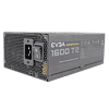
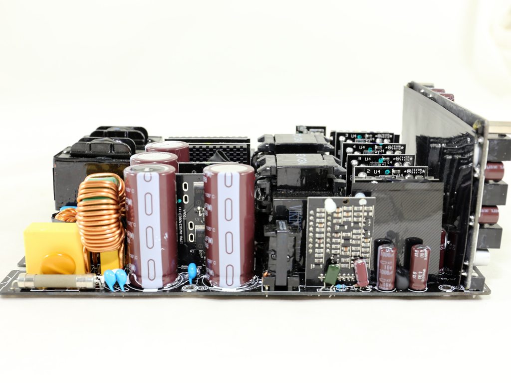
The platform is the same as in the G2 ad P2 of similar capacity. It uses a cutting-edge design with a bridgeless APFC converter that employs a large number of FETs and boost diodes since the rectification process takes place there. The secondary side uses a synchronous design where a large number of FETs rectify the +12V rail and two Voltage Regulation Modules (VRMs) generate the minor rails. The PCB is enormous and doesn't have a heatsink. Considering this unit's capacity, this is an amazing feat made possible because the unit is incredibly efficient, which reduces the thermal load significantly.
The small PCB behind the AC receptacle is free of transient filtering components. The latter are installed on the main PCB and include three pairs of Y caps, a pair of X caps, an MOV, and two CM chokes. All in all, the transient filter is complete.
The only bridge rectifier this unit uses is a US30K80R that operates when the unit is in standby. As such, this strong bridge rectifier is only used by the 5VSB rail.


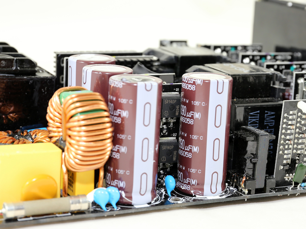
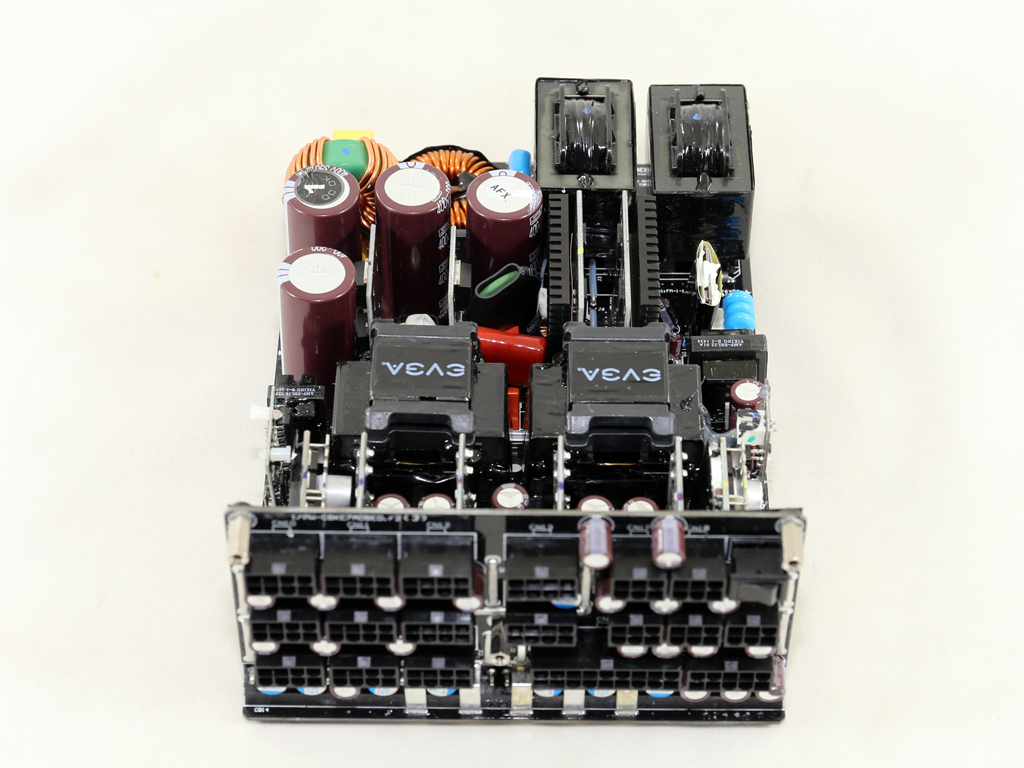
The APFC converter includes four daughter boards that are full of components and two large coils. These work in pairs and each holds four Infineon FETs and two IDL10G65C5 boost diodes. The incoming alternating current (AC) voltage is rectified in the APFC converter and is executed by FETs, which lose much less energy than the bridge rectifier's diodes. This is the only approach that allows for Titanium efficiency in such high capacity PSUs. There are also four parallel Nippon Chemi-Cons, the bulk caps (400 V, 390 uF each or 1560 uF combined, 105°C, KMW), and our tests proved that their combined capacity is enough to meet the unit's needs.

The PFC controller, a proprietary IC code-named SF29603, is installed on this shielded board.

An NTC thermistor protects the unit against large inrush currents, and it has its own relay to cut it off the circuit as needed.


Two vertical boards hold all the main switchers, four Infineon IPP50R140CP FETs arranged into a full-bridge topology. Also, an LLC converter is used to boost efficiency.
There wasn't enough space for a single, huge main transformer, so two in parallel were used instead.


Four vertical PCBs in the secondary side host the FETs that regulate the +12V rail. In total, twelve Infineon BSC027N04LS G fets are used in an effort to balance the load among them and lower energy losses, especially at high loads.
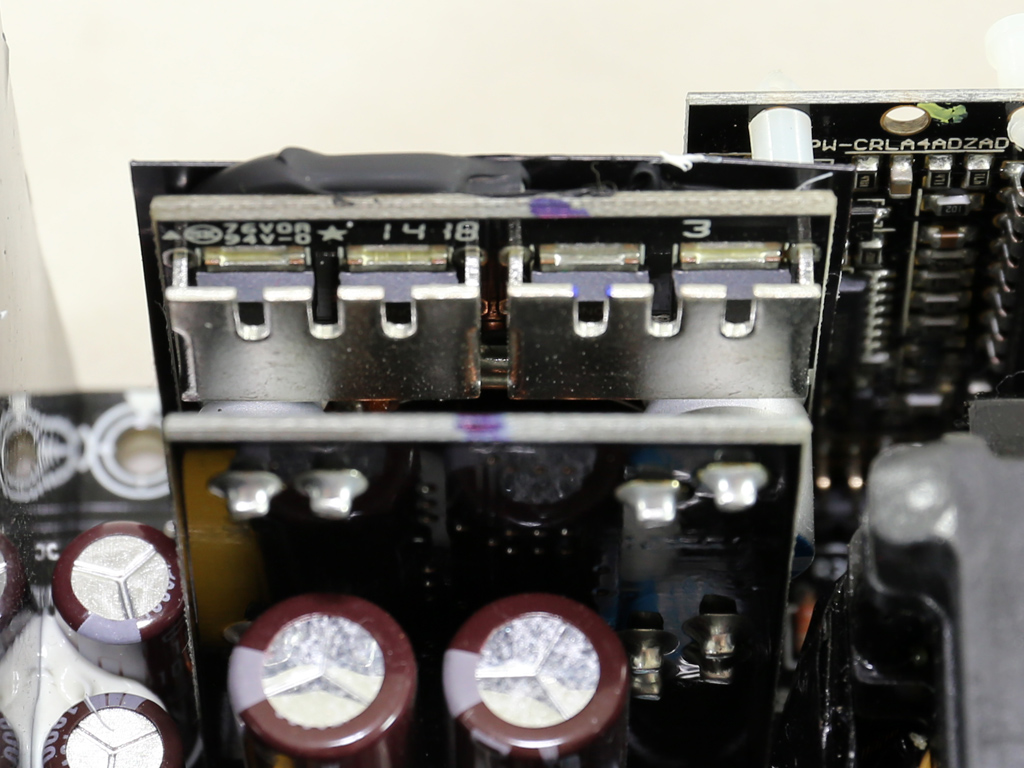


Two DC-DC converters handle the minor rails. Each converter uses four Infineon IPD060N03Β FETs.


Right next to a DC-DC converter is the fan control circuit's PCB, along with a Mospec S10C60C SBR that generates the 5VSB rail. This particular PCB also hosts an LM324ADG. The standby PWM controller only has a number written on it, 29604, which didn't proved useless in identifying it.
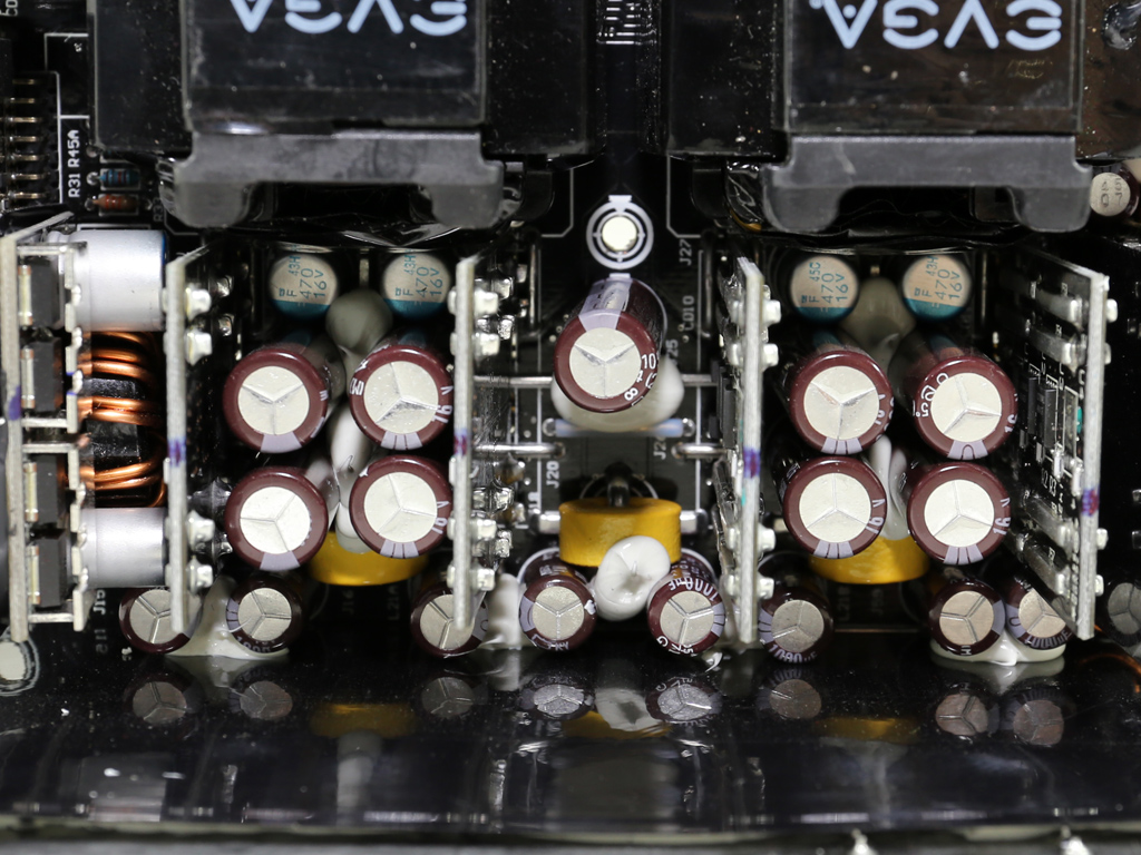

All filtering capacitors in the secondary side, both electrolytic and polymer, are by Nippon Chemi-Con, which is a quality choice for a PSU that is backed by a ten year warranty.


A small vertical PCB in the primary side holds an AA9013 IC for which there is no information available. There is also a well-hidden LM324ADG on the same board.


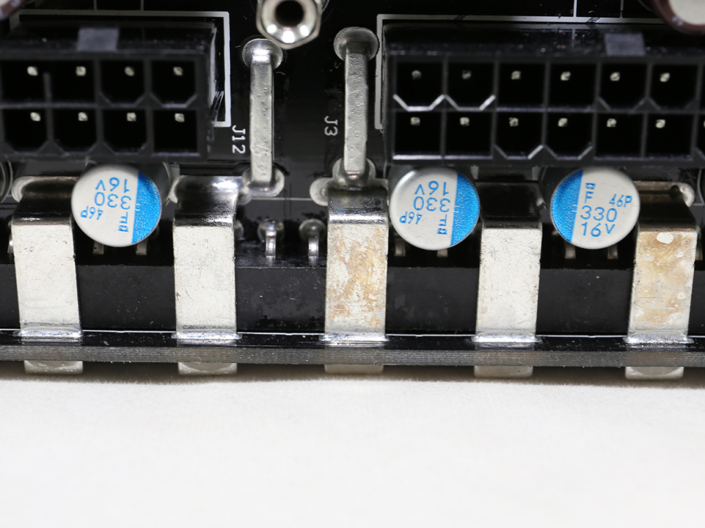

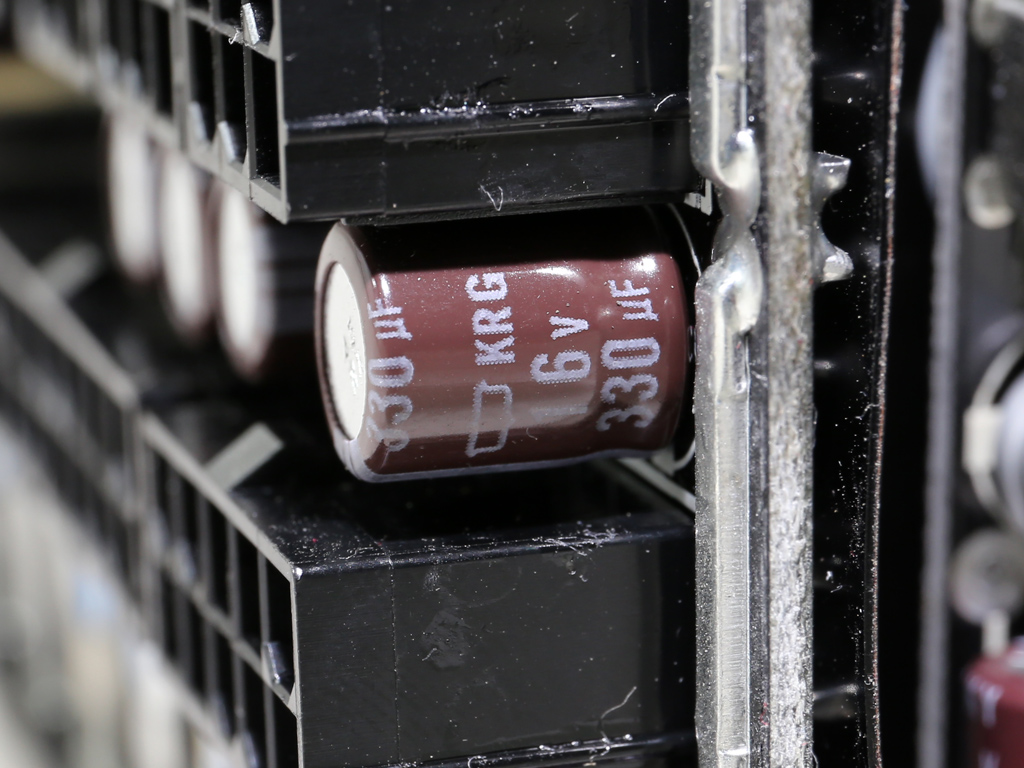
The modular PCB's rear side is insulated by tape. Many filtering capacitors are installed on its front. Both electrolytic and polymer, all of these are by Chemi-Con. Compared to Chemi-Con's KY caps on the main PCB, these electrolytic caps aren't of very high quality, though. The KRG caps have a lifetime of 1000 hours at 105°C, while the KY caps have a lifetime of 5000 hours at the same temperature. However, the caps in this area aren't taxed as much since they only help with ripple filtering. The caps on the main PCB take care of all the other filtering duties.


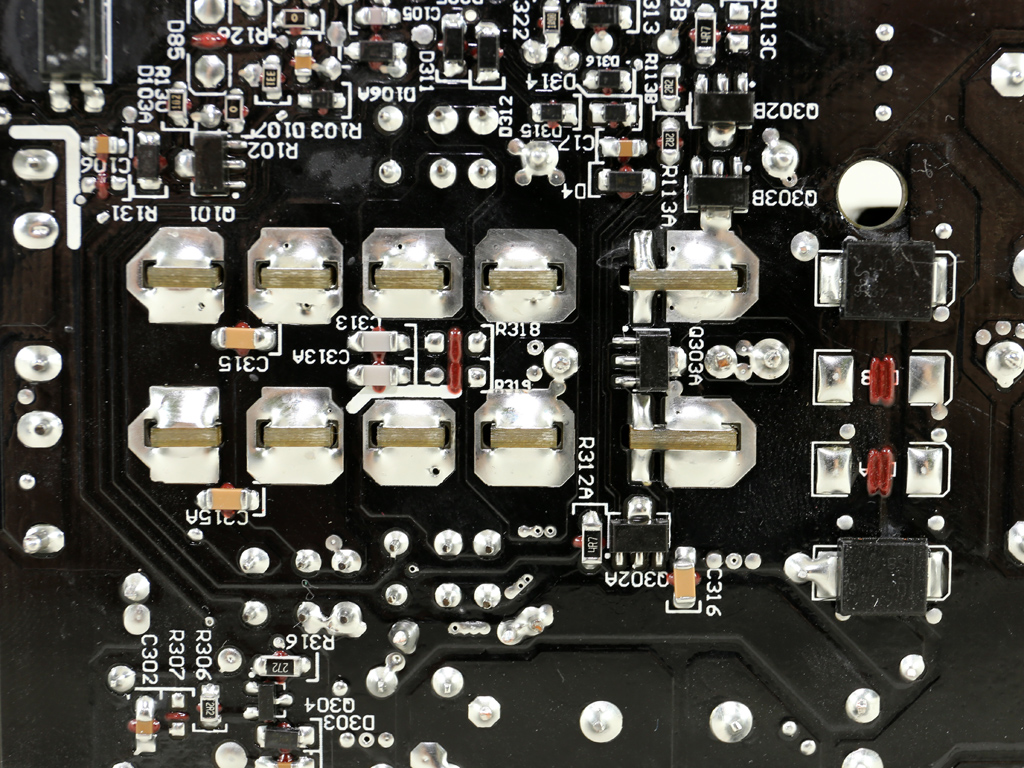

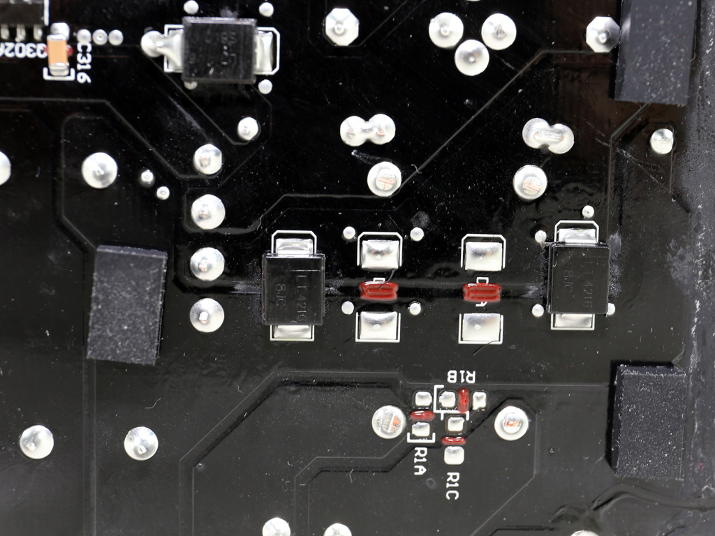
Soldering quality in the primary side is good.

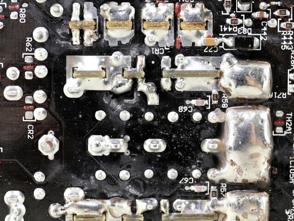

Soldering quality in the secondary side is mediocre. As seen in these pictures, last minute enhancements had to be made to some of the solder joints in this area. These were most likely made by hand.

The cooling fan is the same as in almost all high capacity SuperNOVA PSUs. It is by Globe Fan, and its model number is RL4Z-B1402512EH (140 mm, 12 V, 0.6 A, 2000 RPM, 153.47 CFM, 39.5 dBA, 70.000 MTBF). This fan is equipped with double ball-bearings for better longevity. This PSU features a semi-passive mode, so the fan won't rev up at light and moderate loads so long as ambient temperatures aren't too high. However, once the fan does start with ECO mode enabled, its fan control circuit will only provide it with a handful of speed profiles. As such, its speed won't vary a lot.
Apr 25th, 2024 17:19 EDT
change timezone
Latest GPU Drivers
New Forum Posts
- TPU's Nostalgic Hardware Club (18463)
- Ubuntu 24.04 LTS released (0)
- im new to throttelstop and i think i messed it up by copying others any hints would be very much aprreciated (2)
- Ryzen Owners Zen Garden (7243)
- What software are you using to monitor CPU temps during gaming session? (15)
- ROG Strix LC III 360 ARG AIO What should the pump speed be? (4)
- Ghetto Mods (4322)
- Legion Pro 7i, i9-13900HX. PL2 limit reason in log file (0)
- Alphacool CORE 1 CPU block - bulging with danger of splitting? (15)
- What are you playing? (20528)
Popular Reviews
- Fractal Design Terra Review
- Thermalright Phantom Spirit 120 EVO Review
- Corsair 2000D Airflow Review
- Minisforum EliteMini UM780 XTX (AMD Ryzen 7 7840HS) Review
- ASUS GeForce RTX 4090 STRIX OC Review
- NVIDIA GeForce RTX 4090 Founders Edition Review - Impressive Performance
- ASUS GeForce RTX 4090 Matrix Platinum Review - The RTX 4090 Ti
- MSI GeForce RTX 4090 Suprim X Review
- MSI GeForce RTX 4090 Gaming X Trio Review
- Gigabyte GeForce RTX 4090 Gaming OC Review
Controversial News Posts
- Sony PlayStation 5 Pro Specifications Confirmed, Console Arrives Before Holidays (116)
- Windows 11 Now Officially Adware as Microsoft Embeds Ads in the Start Menu (106)
- NVIDIA Points Intel Raptor Lake CPU Users to Get Help from Intel Amid System Instability Issues (106)
- AMD "Strix Halo" Zen 5 Mobile Processor Pictured: Chiplet-based, Uses 256-bit LPDDR5X (101)
- US Government Wants Nuclear Plants to Offload AI Data Center Expansion (98)
- AMD's RDNA 4 GPUs Could Stick with 18 Gbps GDDR6 Memory (87)
- Developers of Outpost Infinity Siege Recommend Underclocking i9-13900K and i9-14900K for Stability on Machines with RTX 4090 (85)
- Windows 10 Security Updates to Cost $61 After 2025, $427 by 2028 (84)