 0
0
Thermaltake SMART 730 W Review
Voltage Regulation & Efficiency »A Look Inside
Before reading this page we strongly suggest to take a look at this article, which will help you understand the internal components of a PSU much better.
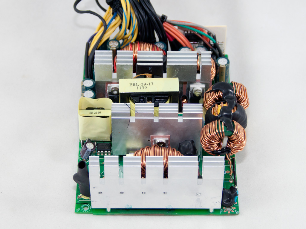
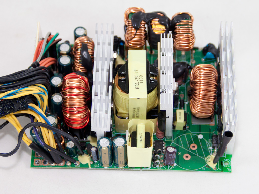


Once we removed the enclosure we looked at a classic double forward configuration using a group regulation scheme in the secondary. Of course, judging from the price of this unit and its efficiency rating, we didn't expect to see cutting edge technology in its internals, but at least an independent regulation scheme in the secondary side would be highly preferable. The OEM of the unit looks to be HEC/Compucase, a manufacturer which we don't encounter very often in our reviews. The heatsinks used in this unit are not so large and the main PCB is very small, especially for the 730W of max power that this PSU can deliver. Finally, as you can see by taking a closer look at the APFC circuit, we removed the bulk cap to unblock the view to crucial components.
The AC receptacle and the On/Off switch are actually soldered on a small PCB. The same PCB houses the first part of the transient filter, one X and two Y caps. On the main PCB we find the second part of the transient filter, three CM chokes, an MOV, one X and two Y caps. The transient filtering stage is complete so let's move on to the rest components.

The bridge rectifier is bolted on the APFC heatsink. Its model number is GBJ 1506 and can handle up to 15A, so it easily copes with this unit's max power. After the bridge rectifier we meet the PFC input capacitor which filters the high frequency ripple of the fully rectified signal.


In the APFC three IPP60R190C6 fets are used along with a Philips BYC10-600 boost diode. The hold up cap is provided by Teapo (470μF, 400V, 105°C).

As main choppers two Infineon IPP60R190E6 fets are used in a double forward configuration.


The combo PFC/PWM controller is a Fairchild FAN4800IN IC. This controller will be soon discontinued by its manufacturer, meaning that it is rather old, so it is suitable only for low efficiency units like this one. The standby PWM controller is a TNY279PN.


In the secondary side passive design is used so the rectification of all rails handle Schottky Barrier Diodes (except the -12V rail which due to its very low output is handled by a conventional diode). The +12V rail regulate four PFR40L60CT while the minor rails are generated through two pairs of SBR30A40CT diodes. Also the presence of only two toroidal chokes is a clear indication that a group regulation scheme is utilized, something that will lead to lower performance in cases where the loads among the rails are highly unbalanced. Finally, all filtering caps in the secondary side are provided by Teapo and all are rated at 105°C.


In the area where all +12V wires are connected to the main PCB we noticed that there are actually two +12V islands on the main PCB, meaning that the +12V virtual rails are two. The first +12V rail uses solid yellow wires while the second uses yellow wires with a blue stripe. Unfortunately we discovered that the EPS connector is powered by the same rail (12V2) that also powers two of the PCIe connectors, something that normally should be avoided in every PSU. If indeed there are two +12V rails, which most likely is the case here, then the power distribution is not optimal.


Housekeeping jobs are handled by a PS223 IC which is installed on a vertical PCB in the secondary side. This supervisor IC supports OCP for up to two +12V channels, matching this way the two +12V rails we spotted in the secondary side.


Soldering quality on the main PCB is good with clean and well made solder joints. Nevertheless we spotted some rather large component leads, a view we hate to see since it can cause lots of trouble (shorts).

The cooling fan has Thermatake's badge on it with TT-1225A model number however with a closer look one can spot the original model number which is DFS122512H (120mm, 12V, 0.28A, 1700RPM, 71.05CFM, 33.87dBA) and figure out the true manufacturer, Young Lin Tech. At low speed the fan is inaudible while at full speed it makes some noise which however is not so loud.
Apr 23rd, 2024 13:43 EDT
change timezone
Latest GPU Drivers
New Forum Posts
- Is there a technical reason that Windows 11 doesn't have built into it battery charge limitation? (34)
- hacked (71)
- after hack (3)
- Unlock the shaders - AMD Radeon RX 560D (326)
- What's an inexpensive AIO product line with a strong pump and low price? (80)
- How to stop thermal thorttling on i7-1165g7 (1)
- No POST, and no display (0)
- Embracer Group is breaking into 3 smaller companies... lol who saw this coming, what a joke (8)
- Cinebench crashed my PC. My Wi-Fi stopped working, and I keep getting a "Please wait" screen when I boot up my PC. (24)
- Which new games will you be buying? (295)
Popular Reviews
- Horizon Forbidden West Performance Benchmark Review - 30 GPUs Tested
- Fractal Design Terra Review
- Corsair 2000D Airflow Review
- Thermalright Phantom Spirit 120 EVO Review
- Minisforum EliteMini UM780 XTX (AMD Ryzen 7 7840HS) Review
- ASUS GeForce RTX 4090 STRIX OC Review
- NVIDIA GeForce RTX 4090 Founders Edition Review - Impressive Performance
- ASUS GeForce RTX 4090 Matrix Platinum Review - The RTX 4090 Ti
- Creative Pebble X Plus Review
- MSI GeForce RTX 4090 Gaming X Trio Review
Controversial News Posts
- Sony PlayStation 5 Pro Specifications Confirmed, Console Arrives Before Holidays (116)
- NVIDIA Points Intel Raptor Lake CPU Users to Get Help from Intel Amid System Instability Issues (105)
- AMD "Strix Halo" Zen 5 Mobile Processor Pictured: Chiplet-based, Uses 256-bit LPDDR5X (101)
- US Government Wants Nuclear Plants to Offload AI Data Center Expansion (98)
- Windows 10 Security Updates to Cost $61 After 2025, $427 by 2028 (84)
- Developers of Outpost Infinity Siege Recommend Underclocking i9-13900K and i9-14900K for Stability on Machines with RTX 4090 (83)
- TechPowerUp Hiring: Reviewers Wanted for Motherboards, Laptops, Gaming Handhelds and Prebuilt Desktops (74)
- Intel Realizes the Only Way to Save x86 is to Democratize it, Reopens x86 IP Licensing (70)