 7
7
Xilence XQ Series 850 W Review
Voltage Regulation & Efficiency »A Look Inside
Before reading this page we strongly suggest to take a look at this article, which will help you understand the internal components of a PSU much better.


We had to remove 14 screws to reach the main PCB. Unfortunately Xilence didn't make this PSU reviewer friendly! The first impression was made by the really small heatsinks on the secondary and the specially designed main transformer which incorporates the +12V fets. The platform includes many modern characteristics and more specific it uses an LLC resonant converter, synchronous rectification on the secondary and the VRMs responsible for the minor rails generation are close to the modular PCB, to restrict power losses. Finally the OEM of this unit looks to be Solytech.

The transient filter starts on the main PCB and includes two pairs of X and Y caps, two CM chokes, a thermistor and a relay to bypass it once the start up phase finishes and finally an MOV. The two parallel bridge rectifiers are two GBU15L06 and each one can handle up to 15A of current. To identify them we had to remove the PFC input capacitor.


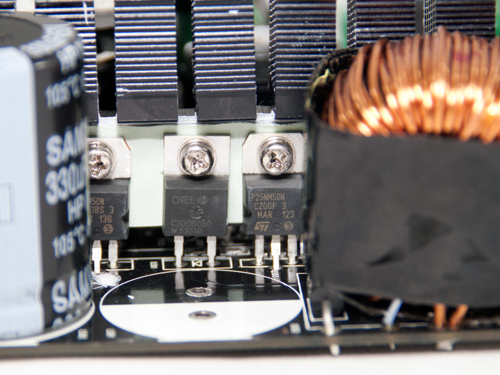
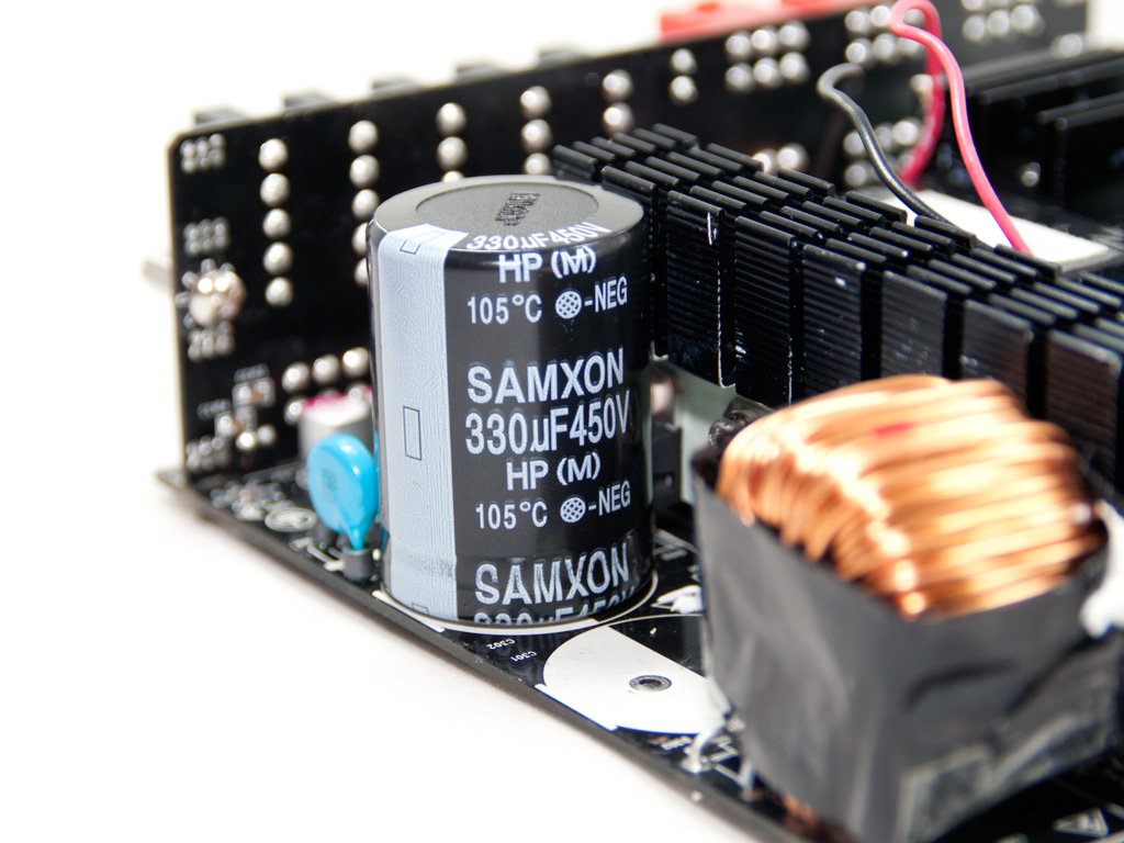

In the APFC three STP25NM50N fets are used along with a C3D06060 boost diode. The two parallel hold up caps are provided by Samxon (330μF, 450V, 105°C), Solytech's favorite capacitor manufacturer. Personally we would highly prefer the use of Japanese caps in such a high priced PSU. As main choppers two STP25NM50N are used.
The main transformer uses a special design which allows the +12V fets to be directly attached to it, something that minimizes energy losses thus boosts efficiency. In total eight IPP037N08N fets are used for the +12V regulation.


The VRMs responsible for the minor rails generation are located on the main PCB and very close to the modular PCB. Each utilizes an APW7073 PWM controller, installed on the solder side of the main PCB, along with four fets.


These four shunts are probably for OCP of the +12V rails. Since on paper there are five +12V rails, an equal number of shunts should exist. Also the protections IC, a SITI PS229, supports OCP only for one +12V rail so most likely OCP is implemented through another IC.


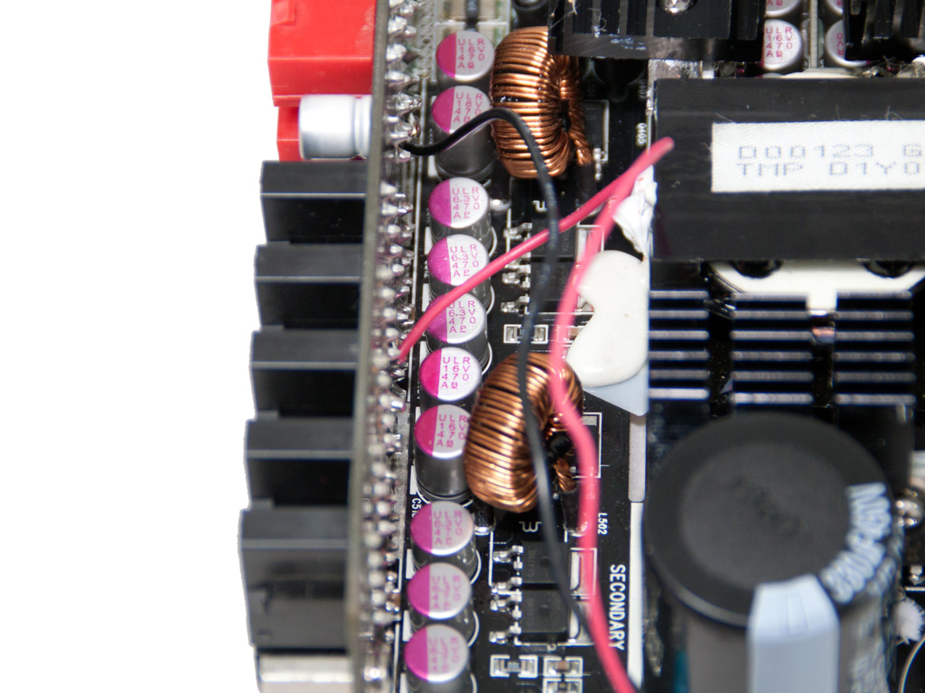

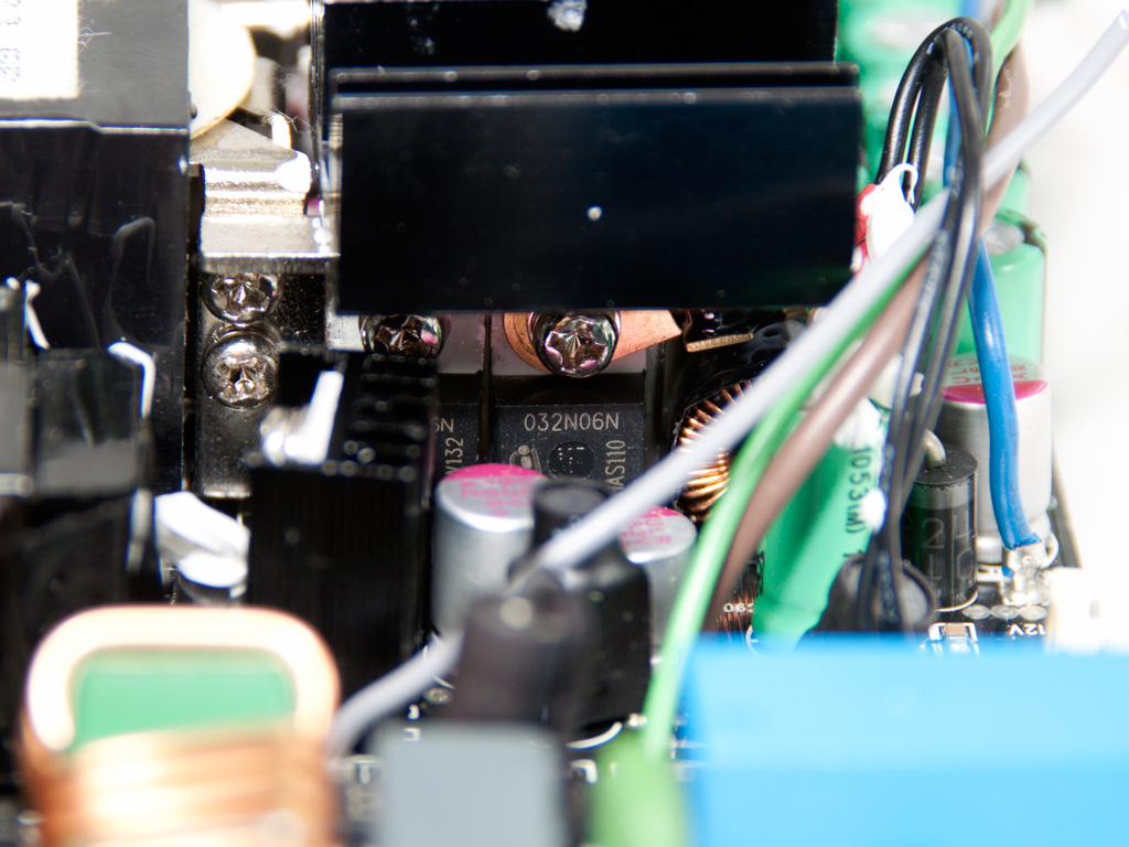
In the secondary side ten electrolytic caps, rated at 105°C, provided by YC (YANG-CHUN) along with many polymer ones (provided by X-CON/Samxon) filter the DC outputs. The electrolytic ones are used exclusively for +12V filtering.
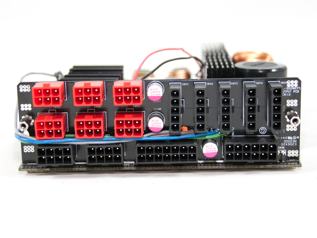
The modular PCB is directly attached to the main PCB via seven bus bars. This way transfer-resistances are reduced and efficiency gets a boost.
Four thin wires transfer PG (Power Good signal), -12V, PS On and 5VSB to the modular PCB. We don't mind for the first three but we would highly prefer a shorter route (e.g. via a PCB trace) for the 5VSB.

Soldering quality on the rear of the modular PCB is quite good. The two wires shown in the photo above power the Power On LED.


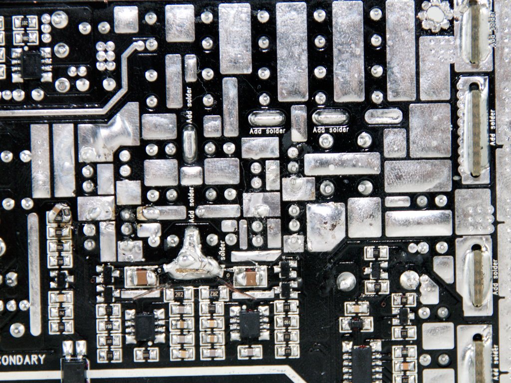
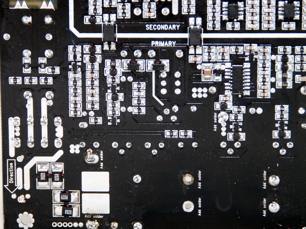
Soldering quality on most parts of the main PCB is very good, but we also spotted several sloppy solder joints. Thankfully we were unable to find a single long component lead, something that means less trouble.


The two cooling fans are provided by Shenzhen Xin Wang Xin electronics and their model number is XWX0615H12B (12V, 0.14A). Despite their small diameter they are pretty quiet since most of the time they operate at reduced RPMs.
Apr 19th, 2024 18:28 EDT
change timezone
Latest GPU Drivers
New Forum Posts
- Roccat Kone AIMO has developed a double left click, when I click it once. Any fix out there? (33)
- AMD RX 7000 series GPU Owners' Club (1067)
- The TPU UK Clubhouse (24738)
- XFX RX580 stock Bios (7)
- Looks like the Z80 is finished (2)
- AAF Optimus DCH Audio Modded Driver for Windows 10/11 - For ALL HDAUDIO Enumerator Chips (642)
- What can be changed in a VBIOS file? (PCI vendor etc) (5)
- Whats your favourite Linux Distro? (53)
- GPU-Z reporting wrong ReBar info for RTX 20 series (1)
- [WIN11] 5700x3d Security processor Attestation: Not supported? (9)
Popular Reviews
- Horizon Forbidden West Performance Benchmark Review - 30 GPUs Tested
- PowerColor Radeon RX 7900 GRE Hellhound Review
- Fractal Design Terra Review
- Corsair 2000D Airflow Review
- Thermalright Phantom Spirit 120 EVO Review
- Minisforum EliteMini UM780 XTX (AMD Ryzen 7 7840HS) Review
- Creative Pebble X Plus Review
- FiiO KB3 HiFi Mechanical Keyboard Review - Integrated DAC/Amp!
- ASUS GeForce RTX 4090 STRIX OC Review
- NVIDIA GeForce RTX 4090 Founders Edition Review - Impressive Performance
Controversial News Posts
- Sony PlayStation 5 Pro Specifications Confirmed, Console Arrives Before Holidays (111)
- NVIDIA Points Intel Raptor Lake CPU Users to Get Help from Intel Amid System Instability Issues (102)
- US Government Wants Nuclear Plants to Offload AI Data Center Expansion (98)
- Windows 10 Security Updates to Cost $61 After 2025, $427 by 2028 (82)
- AMD "Strix Halo" Zen 5 Mobile Processor Pictured: Chiplet-based, Uses 256-bit LPDDR5X (82)
- Developers of Outpost Infinity Siege Recommend Underclocking i9-13900K and i9-14900K for Stability on Machines with RTX 4090 (82)
- TechPowerUp Hiring: Reviewers Wanted for Motherboards, Laptops, Gaming Handhelds and Prebuilt Desktops (72)
- Intel Realizes the Only Way to Save x86 is to Democratize it, Reopens x86 IP Licensing (70)