• Welcome to TechPowerUp Forums, Guest! Please check out our forum guidelines for info related to our community.

Help! Locating bios/flash chip

merqs07

New Member
Joined
Aug 26, 2015
Messages
11 (0.00/day)
Hi everyone! This my first time posting here at TPU.

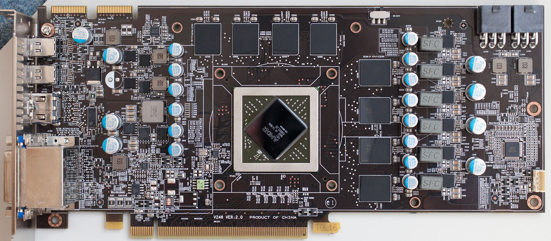
This site really give me alot of insights about my video card. So recently i flash my msi r6950 pe/oc with an asus one and after rebooting it has to display. So i tried fixing it using my sapphire vapor-x 5770. And accidentally flashed my back-up rom to my vapor-x so my 2 cards are bricked. T.T

Can anyone help me locating where are the bios / flash chip so that I could start hard modding them because as I do my research it's the only way. I had to buy a soldering iron for me to do this. Then i saw some many chip with 8 pins. Tried asking uncle google but still no luck. So now here I am asking for help to you guys.

Here are the pictures of the back plate of my cards.

MSI r6950

IMG_20150825_235858.jpg


Sapphire vapor-x 5770

http://s1213.photobucket.com/user/merqs07/media/IMG_20150825_235425.jpg.html

Thanks in advance and more power to TPU :)
 
bottom rectangular green sticker I think
 
If I'm not mistaken your 6950 should have a BIOS switch for a second bios wich should allow you to boot the card and reflash your backup to it.
 
If I'm not mistaken your 6950 should have a BIOS switch for a second bios wich should allow you to boot the card and reflash your backup to it.

Sadly the Twin Frozr II version doesn't have it. For whatever reason MSI didn’t include it on that card, but they fixed that “mistake” on the Frozr III edition.
 
Sadly the Twin Frozr II version doesn't have it. For whatever reason MSI didn’t include it on that card, but they fixed that “mistake” on the Frozr III edition.
But his sticker says twinfrozr 3
 
The only problem now is my Sapphire vapor-x 5770. Tried flashing it but the atiflash can't find the adapter. X.x
 
Anyway my sapphire vapor-x 5770 can't be detected by the atiflash. This one really need to be hard modded. Can anyone help me determining where is the bios flash chip on this one?

Here is the picture of my sapphire vapor-x 5770.

IMG_20150825_235425.jpg
 
can't tell from your picture I would need the part numbers printed on the chip the bios chip
write down all the model and numbers printed on the top of the chips and post them

it should read something like SSGT 25VFG**** if its a rom chip
may also be a PM* either way get the part numbers

@merqs07
 
Last edited:
can't tell from your picture I would need the part numbers printed on the chip the bios chip
write down all the model and numbers printed on the top of the chips and post them

it should read something like SSGT 25VFG**** if its a rom chip
may also be a PML either way get the part numbers

@merqs07
Ok lemme take a look at it later when I got home from work. I better have to buy a magnifying lens too for me to see those since they were too tiny to read. Thanks you soo much mate. :-)
@OneMoar
 
can't tell from your picture I would need the part numbers printed on the chip the bios chip
write down all the model and numbers printed on the top of the chips and post them

it should read something like SSGT 25VFG**** if its a rom chip
may also be a PML either way get the part numbers

@merqs07

Ok back. Here are the names of the chips with 8 pins.

- uP7701U8 PGP98J (2 Chips with same name)

- Pm25LV010 AE0944 M16961LG

-uP6101BU8 VGB9A6

@OneMoar
 
Ok back. Here are the names of the chips with 8 pins.

- uP7701U8 PGP98J (2 Chips with same name)

- Pm25LV010 AE0944 M16961LG

-uP6101BU8 VGB9A6

@OneMoar
The uP is the umm..NOT BIOS..power delivery.
Having mental block. :(
PWM controller IC.
 
Thanks for all the replies guys. I'll start my quest tomorrow it is late night here. I'll gonna keep you guys posted when I succeed in recovering my sapphire card. :toast:
 
Pm25LV010 is the one you want
short pin 8 to pin 1 should make the chip flashable
shorting pin 1 to 3 should disable write protect
you may need todo both and remember you need to be-able to easily access your wiring to disconnect then bridge

@merqs07 oi HOLD IT STOP AND READ BEFORE JUMPING STRAIGHT IN
I HIGHLY RECOMMEND YOU PURCHASE A TEST CLIP Instead of soldering

unless you are a practiced hand with a soldering iron You will permanently damage something or make the problem worse
you can get a test clip and jumper wires from the links below
http://www.digikey.com/product-detail/en/5250/501-1311-ND/745102 > soc8 test clip
https://www.adafruit.com/products/266 >female jumper wires (optional but will make your life easier )
 
Last edited:
Pm25LV010 is the one you want
short pin 8 to pin 1 should make the chip flashable
shorting pin 1 to 3 should disable write protect
you may need todo both and remember you need to be-able to easily access your wiring to disconnect then bridge

@merqs07 oi HOLD IT STOP AND READ BEFORE JUMPING STRAIGHT IN
I HIGHLY RECOMMEND YOU PURCHASE A TEST CLIP Instead of soldering

unless you are a practiced hand with a soldering iron You will permanently damage something or make the problem worse
you can get a test clip and jumper wires from the links below
http://www.digikey.com/product-detail/en/5250/501-1311-ND/745102 > soc8 test clip
https://www.adafruit.com/products/266 >female jumper wires (optional but will make your life easier )

:laugh:I tried soldering it, but I'm having a hard time connecting the wire from pin1 to 8 so I got back here in the forum to ask what kind of solder to use.

Anyway, can I purchase those in a local electronic shop?

Thanks again mate! :D

@OneMoar
 
Hi

I'm having a hard time connecting the wire from pin1 to 8 so I got back here in the forum to ask what kind of solder to use
None

Use wire from an old 80pin IDE cable or very fine insulated wire
1 & 8 pin wire loop vga vbios.jpg
Loop wire under the leg's of pin 1 and pin 8
Loop Wire Pin1 & Pin8.jpg
or attach wire across top of the Vbios chip with bubble-gum; just ensure the wire is touching the legs
[Note: the wire only has to be in place for a short time to bring the voltage low; before cutting wire or breaking the connection]

+1 OneMoar use clips

atb

Law-II
 
Last edited:
Hi


None

Use wire from an old 80pin IDE cable or very fine insulated wire
View attachment 67616
Loop wire under the leg's of pin 1 and pin 8
View attachment 67617
or attach wire across top of the Vbios chip with bubble-gum; just ensure the wire is touching the legs
[Note: the wire only has to be in place for a short time to bring the voltage low; before cutting wire or breaking the connection]

+1 OneMoar use clips

atb

Law-II

Good thing I saw your post before leaving the office. I looked for scrap stuff in our storage for IDE cables and gladly found one. Hehe! Here goes nothing! XD

Thank you so much for the advice mate! @Law-II
 
digikey offers global shipping ...
again one slip up with the soldering iron and you will be all done
if you lift one of the legs off the pcb its gonna be near impossible to re-attach it
 
Guys thank you soo much!!!

All my cards are back in one piece. I able to fix my sapphire card without soldering it.

Kudos and cheers! :toast::toast::toast::lovetpu:
 
Hi

Great to see the cards up and running once again :toast:

atb

Law-II
 
Back
Top