• Welcome to TechPowerUp Forums, Guest! Please check out our forum guidelines for info related to our community.

vintage Detectron miniATX case mod

fickludd

New Member
Joined
Sep 28, 2014
Messages
13 (0.00/day)
Hi all,

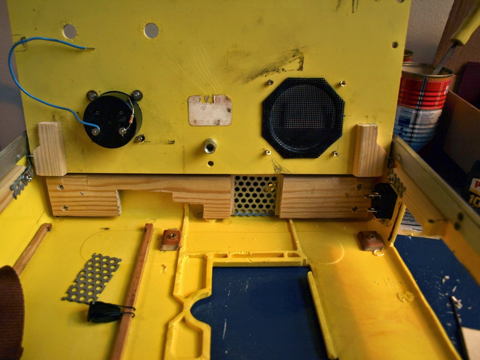
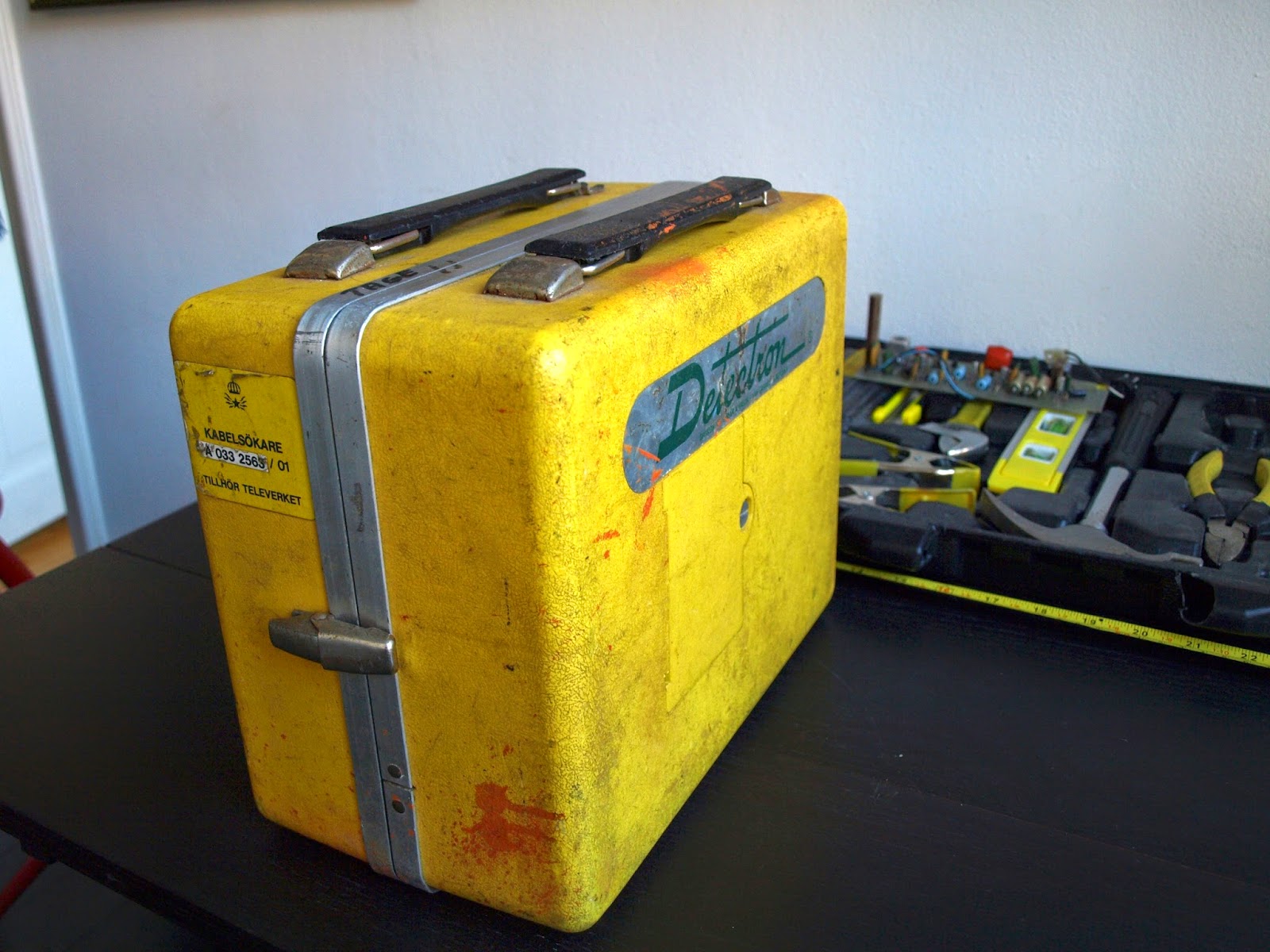
I'm quite new to case modding, but recently decided to convert a very cool tool, called a Detectron, into a miniATX based computer. In short, I've ordered the following rig:
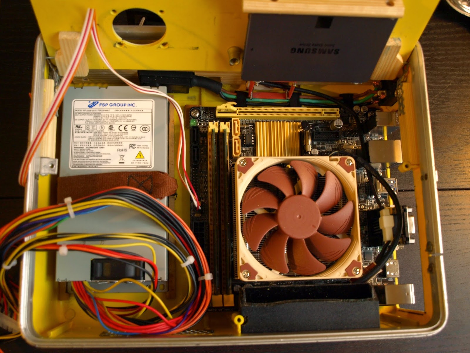
  • ASUS H81I-Plus LGA1150 Socket, LGA1150 Socket Mini ITX
  • Intel Core i5 4570S / 2.9 GHz processor
  • Samsung 840 EVO MZ-7TE250 250GB 2.5" Serial ATA-600
  • FSP 1U 220W ATX12V
  • Kingston ValueRAM DIMM 240-pin 8GB 1600MHz CL11
  • Noctua NH-L9i
  • Noctua NF-A4x10 FLX
If you want to follow the progress, I'll be posting regularly onto my blog, but here are some pics to get you started. These also gonna be summaries of progress here. It's going to be a squeze go fit everything in, and I'm also planning to make the original knobs and gauge do stuff. Stay tuned!

P9081702.JPG


P9081688.JPG
P9081703.JPG
 
nice box, wait for further
its a nice mod
 
What a great case for a mod! Looking forward to your progress! :)
 
Thanks for the encouragement!

Didn't want to post without progress, but now I finally got the components. Did most of the cutting and gutting of the old case this weekend, to make room for the motherboard. Things will get very tight. See more on blog.

PA041786.JPG

PA041789.JPG

PA011770.JPG
 
I likey! I thought about this when I had my old tough pelican case but ended up selling it. Looking good so far!
 
So you're not touching the actual instrument then?
 
Well no, the only thing that will be left is the analogue ampere-meter which will be used. I need to change the logic for all the inputs because the old electronics are just too large to fit inside along with the mobo and PSU. As for the rest - don't really know what to do with it?
 
More progress - now made mount points for motherboard. More on the blog.

Does anybody have any tips for how to attach the PSU? I don't wanna make holes in the case, but it still needs to sit right on top of the case.

PA131822.JPG

PA131824.JPG

PA131826.JPG
 
You could make some kind of mount by using L-brackets and epoxy
 
Hmm, not quite sure how you mean, but I have a (non-conventional) solution on way now. Update soon =).

Does anyone have a suggestion for where to get a suitable power button for the case? I was thinking a regular off-(on) switch, but they seem to stick in too far on the inside. Tips are welcome!
 
What size PSU you going to try? SFX? MITX?
 
umm.. personally, i consider plexy to hold the board and the psu then the plexy glued to case
 
thanks for all the suggestiongs. The large problem here is that the PSU is 40 mm high (its a FSP 1U 220W ATX12V, 81,5x150x40,3mm), and the entire inside of the case only 61 mm. Since I need to put some I/O board on top of the PSU, a mounting construct need to use really minimal space.

Made some plans for the inside on the blog, which is summarised in the following pic. Will be a post on the selected PSU attachment soon.

detectron_midway_planning.jpg
 
Whatever kind of bracket you can find from the local hardware store that would work:

https://www.google.com/search?q=l-b...uzyASBhIDQDQ&ved=0CAkQ_AUoAg&biw=1904&bih=955

Glue/epoxy one side of the bracket to the case, then use the other side of the bracket to run the screw through to hold the PSU. Also, for the power switch, usually a momentary switch is used to turn the board on.

Ah, I see what you mean! That's gonna be a bit hard though, because there is no room to actually perform the screwing (ahum...).

Yeah, I meant a momentary switch that is off normally, but momentarily on when pushed (ergo off-(on)). Something like this.


Made the PSU post, check it out!

PA201860.JPG
 
Hi everyone,

Long time no update, and lots of things have happened. I'm trying to catch up with mostly pics on the blog, but in short I have
  • Finally test-ran all the components!
  • made a backpiece for mounting the case fan. This was also supposed to be used for attaching hinges for the lid, but that didn't work.
  • Made hole and attached power external interface
  • Made 2 air inlets and 1 of 2 air outlets.
  • constructed hinges. This took something like 5 different attempt before arriving at the final design, involving many iterations of careful gluing followed by careful testing and not so careful swearing.
Some pics to summarize:
PA151849.JPG

PA251881.JPG

PA281906.JPG

PA311934.JPG

PA311933.JPG

PA311932.JPG

PA311935.JPG
 
Last edited:
i dunno why it reminds me of chernobyl
 
heh, yeah I guess the esthetic is going in that sort of direction. Maybe I should put in a Geiger counter just to be sure =).
 
You could put in some kind of dial meter that responds to HDD activity or processor usage.
 
Hey, I will! See that gauge on the left in the second pic in this thread? That will show CPU-usage / RAM usage / HDD space used. It's gonna be awesome.

Soon update with cablework + powerbutton done.
 
It's me again.

Did a lot of work of the cabling, and added a powerbutton.

Sorry for the somewhat crappy pics.

Ran into some new issues though, that I would love some input on. The system now runs, meaning that the cable work seems solid. However I get heat issues, idle CPU-temp stabilizes at 48 C when the lid is closed and 35 C when open. Therefore it should be case ventilation or similar that is needed. Any ideas on how to solve this: where to add case fans / ventilation?

Thanks!

PB151988.JPG

PB182056.JPG

PB182059.JPG
 
you may add small holes to help the hot air comes out
or you may add intake fans, just small fans to give your rig fresh air
 
Last edited:
Back
Top