• Welcome to TechPowerUp Forums, Guest! Please check out our forum guidelines for info related to our community.

x58 xeon x5675 overclocking help needed with high speed mem

That's unconfirmed rumor that some people spread. Makes absolutely no sense. It's hard not to be in 0.5v range.
It's meant to be hard to NOT be within 0.5V range.
You are meant to use CPUs, not kill/damage them on first boot lol.

Otherwise, why would Intel put a 1,65V warning, and how at the same time 1,8V+ DDR3 memory voltage could ever work (without killing CPU's IMC on the spot or within minutes) ?
 
Last edited:
Lots of ram starts @ 1.65v. If you do go over 1.65 to say 1.75v there’s no problem with giving qpi a little bump. There is your .5v assuming stock qpi voltage is 1.2v.
 
The 0.5v rule is rubbish someone made up. There is one rule and it's "DDR with voltage 1.65v and above could damage the processor".

QPI/IMC original voltage is 1.15v, but was boosted by OEMs to 1.2v for DDR 1333/1600. More than 1.3v may damage IMC if used 24/7.

Latest DDR3 chips don't need voltage higher than 1.5v. You can hit 2000 MHz and above with the right timings. Just a pain to find. Voltage boost will add just 50 MHz. Samsung are considered the best.

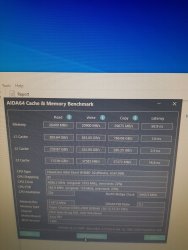
20200717_013508.jpg 20200717_013137.jpg

Cheapest DDR3 1600 modules. Default voltage of 1.5v. You don't need to fry the memory or IMC with insane voltage.
 
Last edited:
Yes the 0.5v margin does exist. SO you say all ddr3 are 1.50v Im sorry not all of them are like that unfortunately so what are you trying to prove??
As for the Dram and QPI Volt to get below the 0.5v Margin based in max voltage according intel datasheet
Xeon x5675
DRAM 1.65v
VTT 1.35v
Result =0.30v
It within the spec
As results varies depending on each cpu
But for the 1.80v on dram while keeping vtt 1.35v it will result 0.45v of margin that why it best to keep in the 0.50v margin
 
Last edited:
There is no reference in the datasheet for 0.5v between IMC/DDR. It makes no sense since it's incredibly hard to break the margin.

1st generation DDR3 modules used 1.65v, but then it changed to 1.5v and 1.35v. The only reference in the datasheet is "don't use memories with 1.65v".

And last, DDR over-voltage makes a small impact of extra 50 MHz (1.5v versus 1.64v). It is better to raise the frequency and relax the timings.

If you run QPI at 1.35v and DDR at 1.8v, don't be suprised to find WHEA errors in the event log. Why not 2.4v and 2.8v? Still within 0.5v so must be fine too.
 
Last edited:
If dram is going that high in voltage that only suitable for world records with Liquid nitrogen set up
How i do the math is dram minus qpi = margin.
You say 2.40v dram while keeping qpi at 1.35 that results overshoot the safe margin = 1.05v that just going to make it degrade even more

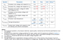
Here the Intel Xeon 5600 series datasheet it stated margin 5%. Dont know why you said you cant find information related
Stated Margin.jpg
 
Last edited:
I was joking and being sarcastic. You just follow the limits per component.

The more recent DDR3 modules don't need a lot of voltage. These are nearly DDR4 chips that just need the right manual timings.

You don't need QPI/VTT at 1.35v. Look at the photos I posted, the one with uncore at 3380 MHz had a memory bandwidth of 32GB/s.
 
I rather follow according to respected voltages labled on per components than abusing it
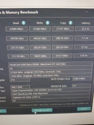
@Regeneration Here mine still beating yours in some areas ignore the ram timing as it a bug in the app that displaying it wrong it running 9-9-9-24
my results.jpg
 
Last edited:
The 5% tolerance has nothing to do with it. It's noted under CPU PLL and DDR min/max voltages.

There is no reference or rule of 0.5v between VTTx and VDDQ.
 
Here the Intel Xeon 5600 series datasheet it stated margin 5%. Dont know why you said you cant find information related
Stated Margin.jpg
Sorry mate, you're reading/interpreting that chart incorrectly. VDDQ max listed as 1.8v is commonly described in most BIOS's as CPU PLL voltage, which is NOT the same as IMC voltage. Intel's spec naming conventions and board makers naming conventions differ greatly, which has always caused confusion.

@steen
You should give a look here for tips and info;
I had forgotten all about this guide. Good stuff!
 
I rather follow according to respected voltages labled on per components than abusing it
@Regeneration Here mine still beating yours in some areas ignore the ram timing as it a bug in the app that displaying it wrong it running 9-9-9-24
View attachment 162427

You reading it wrong.

GAGA.png

You should look at memory write/read/copy/latency.

Mine are at 1.50v and can be pushed further.

Why the fonts aren't aliased? nice cheating attempt.
 
You calling me a cheat the cheek of you i just screenshot it and cropped it and posted it so you might well be cheating the results using a camera and photoshopping crap out of it
 
Last edited:
You guys worry too much! Just send er boys. I got a decade out of mine and she still pulls fine. And the voltages I was using would be considered abuse by some and normal by others :laugh:
 
Im not worried at all
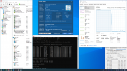
Heres mine as it considered safe in my view
New Bitmap Image (3).jpg
 
This to me is completely safe :toast:

Linpack 4200.PNG
 
You guys worry too much! Just send er boys. I got a decade out of mine and she still pulls fine. And the voltages I was using would be considered abuse by some and normal by others :laugh:
This to me is completely safe :toast:

Linpack 4200.PNG
Those voltages are not problematic. Those are perfectly acceptable for long term use. I'd say the RAM voltage is the only "iffy" one and at 1.6v you're likely ok.
Im not worried at all
Heres mine as it considered safe in my view
View attachment 162434
AH! This is a good illustration. Ok, in this screenshot, the "QPI/DRAM Core Volt" is the same as the "QPI PLL" in the bios. The IMC is a part of the QPI. When you set the QPI PLL to one setting and the "DRAM Bus Voltage" to another voltage, they are interconnected and if either one is set to high they can cause an amplification effect through the IMC because of the way the voltages are handled. In the case of the above photo, the "QPI/DRAM Core Volt"(QPI PLL) is set for 1.3v, a little high, but reasonable voltage and the "DRAM Bus Voltage"(RAM voltage) is set to 1.64v which does not exceed the voltage limits. So in this situation, the voltages are going to be ok for long term use, if a bit above the upper limit. However, If the QPI PLL voltage was set to say 1.325v and the RAM left at 1.64v, you would then have a higher average voltage running through the IMC because of the amplification effect. With each step up from either of those voltage points the amplification effect begins to increase at a curve. This is why RAM voltage is so critical to keep under 1.65v. This problem was a design quirk that Intel had to redesign with later CPU generations.
 
I had it set for 1.6 due to the mix I was using. I had 2x4 and a single 2, the 8gb set only needs 1.5v and the other stick is some older bbse.
 
My is Corsair XMS3 CMX4GX3M2A1600C9 at 1600mhz according to the sticker label on it it requires 1.65v to run at that speed. So i dont get where the 1.50v at 1600mhz.

In that screenshot is the same as the bios for voltage setting there is no mentioned of QPI PLL

According to to the second post on this link it stated DRAM Voltage : Max difference between QPI/DRAM and DRAM itself is 0,5V (above that, you can insta-kill CPU).
 
Last edited:
I have the same CPU/MoBo setup as you and same bios revision why dose your bios show as UEFI in AIDA 64
That board I have does not do UEFI as in AIDA 64 report it stated UEFI Boot : No
 
I saw this thread bumped up again and noticed that I had posted before back on page 2 post #30...

Last year I was having trouble getting my setup to memory train/post at higher speeds with 3x8GB sticks on my X58? I figured that I would take another look. I was able to dial in 1600+ and 1900+ memory settings with this kit but @2133 speed it was again failing to train/post. I was looking at the XMP profile in AIDA64 and noticed that TRFC was specified @278. The BIOS on this board has a max setting of 275. I changed it from AUTO to 275... Set the primaries to 9-11-11-31 and left all the other secondary settings on AUTO. Saved and restarted the computer and then a successful memory training and boot into BIOS!

1644C7> 1918C9> 2144C9:
W3690 3X8GB 1644C7.PNG
W3690 3X8GB 1918C9.PNG
W3690 3X8GB 2144C9.PNG
 
That strange because I double checked aida64 the latest version it said uefi boot = no as the asus p6x58d-e never came with uefi bios at all
I know that's strange I thought maybe you were using a USB UEFI boot devise to run NVME M.2 PCIE SSD
 
Back
Top