• Welcome to TechPowerUp Forums, Guest! Please check out our forum guidelines for info related to our community.

8 Pin PCI-E connector

Random Murderer

The Anti-Midas
Joined
Dec 6, 2006
Messages
6,974 (1.03/day)
Location
Florida, A.K.A. the Sweatbox
System Name TOO MUCH RADIATOR! | The TV Box a.k.a. The Shoebox
Processor Core i7 4930K @ 4.5GHz | Core i5 6600K @ 4.5GHz
Motherboard Asus X79 Rampage IV Extreme | Asus Z170i Pro Gaming
Cooling Custom water on CPU and GPU, dual 360mm radiators | Corsair H80i
Memory 4x 8GB G.Skill TridentX DDR3-1600 | 2x 4GB G.Skill RipJaws 4 DDR4-3000
Video Card(s) Sapphire AMD R9 295x2 | PowerColor AMD HD7970
Storage Samsung SSD 830 256GB, various others | 2x 1TB Seagate Barracudas in RAID1
Display(s) Dell U2713HM 2560x1440 IPS | Panasonic TC-L32E5 1080p IPS TV
Case Thermaltake Suppressor F51 (stripped down to hold two radiators) | Cooler Master Elite 130
Audio Device(s) RM-DAC -> Xiang Sheng 708b -> Sennheiser HD650 | HDMI sound device on 7970
Power Supply LEPA G1600-MA 1600W | Corsair CX750M 750W
Software Win 10 64
Benchmark Scores over 9000 BungholioMarks, "Bitchin' Fast"
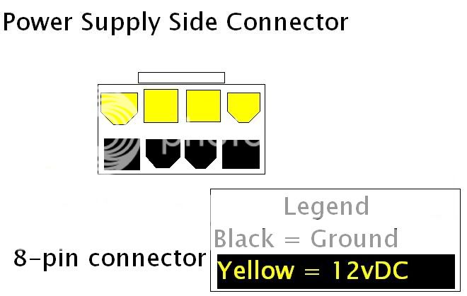
NOTE: Scroll to the bottom of this post for the correct diagram.


Ok, to start off, help on this would be greatly appreciated.

I'm trying to get a pin-out of the 8-Pin PCI-E connector for those of us who would rather make one than buy one, or who can't find one to buy (if anyone knows where to buy one, that would be good too).

So far, I have the original 6-pin pin-out thanks to our own W1zzard!
here's my more in-depth version, albeit made in paint...
6pin.jpg


Here's what I have on 8-pin so far, I don't know what the rails are, but the shape of the pins is a start...
8pin.jpg


I will keep this post(and the above image) edited as we find out more.


EDIT:
COMPLETED!!!
8pin2.jpg


EDIT:
After further research and ample time of the cards that require these being released, the diagram I made was found to be wrong. I used a picture of a 6 to 8 pin adapter, and that company must have color coded the wires incorrectly. Thanks to KennyT772 we have an up-to-date, CORRECT diagram.
pcieplugdiagramoa5.png
 
Last edited:
OneCool said he tried running a 12v+ to the other pin, and it didn't work.

Can anybody confirm this?
 
OneCool said he tried running a 12v+ to the other pin, and it didn't work.

Can anybody confirm this?

he said so about the 2900xt, and we're not even sure if it just his card or not. verificataion would be appreciated.
 
afaik. to enable overdrive the 2900 xt needs to "see" the 4th ground pin connected, not the +12v one
 
Would there be any benefit to attaching the 12v+, especially with stock cooling?
 
ati says better overclocking. i seriously doubt it, but if you want to use ccc overclocking you must have the 4th ground connected for the overdrive tab to be visible
 
afaik. to enable overdrive the 2900 xt needs to "see" the 4th ground pin connected, not the +12v one

Yeah that's all.

As far as the extra 12v line I seen know deference in OCing at all
 
pcieplugdiagramoa5.png
.

The correct diagram made in paint. Correct pinouts and socket, the current diagram at the top of the page is incorrect in both.
 
Last edited:
I want to use molex :(
 
HAHAHAHAHA!!! BOTH extra pins are ground. Talk about a marketing scam. lol
 
found adapter: converts 6-pin to 8-pin.
$9.99 but shipping to me is like another $8 :banghead:
Anybody seen cheaper?
http://www.frozencpu.com/products/6088/cab-97/6_Pin_PCI-E_to_8_Pin_PCI-E2_Adapter_Cable.html?tl=g11c28#options

I looked and can't find anything cheaper myself - just ordered one. I'd prefer to see one with an additional 4-pin Molex draw, but two dedicated 6-pin pci-e connectors should do it... My system (X1950XTX) now draws 320 Watts under load (measured with Kill-A-Watt). And thats with a single 6-pin connector.
 
Excuse my ignorance not having a 2900 card, but for those who have not got the 8 pin PCI-E....what proggie are you using to overclock?
 
Find em on Ebay. Way cheaper.
 
Atitool, ati clock set, tray tools, i think rivatuner works too.
 
Talk about not understanding electronics. Obviously the current on those pins can be pretty high, therefor the extra ground.

Who knows... I *wish* someone would test that, I don't have the equipment. The ATX std wire guage may or may not support it - the question is what amps the pins draw - for sure.
 
In order for a PSU to be pci-e 2.0 certified the 8pin power cables have to be higher gauge wire, enough so they can handle like 4amp per wire. That is easy for even 22ga wire but some cheaper units cannot output this kind of amperage over each wire. 12.5amp over 3 wires is quite a bit a juice so instead of just requiring higher gauge all around, they added 2 extra grounds making it only 2.5amp per ground. This allows smaller gauge ground wire to be used saving cost and sets an easy way to check if the power supply is pci-e 2.0 compliant.
 
In order for a PSU to be pci-e 2.0 certified the 8pin power cables have to be higher gauge wire, enough so they can handle like 4amp per wire. That is easy for even 22ga wire but some cheaper units cannot output this kind of amperage over each wire. 12.5amp over 3 wires is quite a bit a juice so instead of just requiring higher gauge all around, they added 2 extra grounds making it only 2.5amp per ground. This allows smaller gauge ground wire to be used saving cost and sets an easy way to check if the power supply is pci-e 2.0 compliant.


Thx Kenny - did you write that or is it a quote?
 
Talk about not understanding electronics. Obviously the current on those pins can be pretty high, therefor the extra ground.
Well, where is the benefit to these extra grounds, when they are just jumped off of the other grounds, as per the photo of the adapter? And, considering that I haven't heard of anyone melting their 6pin connectors, I seriously doubt there is any real benefit to the 8pin, unless, of course, your psu manufacturer cheaped out on the wire gauges. If that's the case, you probably should've bought a better psu to begin with. My understanding of electronics is what lead me to deduce that this is a scam.
 
wait now, I just thought of a fun thought. If the extra ground is to help with the "high current" coming off of the pins, doesn't that mean that the yellow wires would melt before the black ones? unless the 2900 has a generator in it, or there is a shortage of ground-pins, What's the point?
 

This can't be right, can it? You can put a 6-pin plug into an 8-pin socket, so if this was right the 12vDC on the 6-pin would be going into the ground of the 8-pin.
 
This can't be right, can it? You can put a 6-pin plug into an 8-pin socket, so if this was right the 12vDC on the 6-pin would be going into the ground of the 8-pin.
Nope, post #9 has the correct diagram.
 
Back
Top