• Welcome to TechPowerUp Forums, Guest! Please check out our forum guidelines for info related to our community.

GeForce 8800 GS/GT/GTS Voltmods

Dar_T,
What frequency you run your card?
What exactly happens when it crashes? Does vGPU drop to near 0 volts?

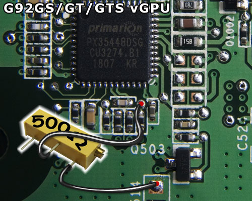
Anyways, for OCP mod, you must use 3 identical resistors each rated for, say, 3000Ω.
 
I ran them at 882/2052/1115. My computer will just shut off and vGpu does drop to 0 volts right after the crash. So I take 3 resistors, each 3000ohms, then solder it onto those three points as depicted in the picture and then leave the other end dangling?
 
Last edited:
Ok, that sure sounds like OCP in work. :)
 
So, just one last thing. I solder a resistor on each of the points and leave the other end free floating. Is that correct? Also what resistor should I use to bypass 1.38v? Btw, largon, thanks for all you help. Cheers. :toast:
 
Err...
I'm not sure what you mean by "leaving the other end free floating"? Normal resistors have two ends and if you solder the parts on the capacitors (that have 2 ends aswell) as per the guide there is no "other end" left to "float free".

OCP mod has pretty much nothing to with voltage tolerance. If your card doesn't like >1.38v there's nothing that can be done.
 
lol sorry I'm totally confused now. In the pic in OP it shows two lines joining between the 3 capacitors does that mean I only need 2 resistors? One resistor linking 1st cap to 2nd cap and then a second linking 2nd cap to 3rd cap? Ohhh now I think I get what you mean. You put a resistor from the brown part to the question mark. Am I right? :p
 
I noticed something weird while I was testing. When both cards are in the OCP is at 1.3v but when one card is in the OCP is at 1.4v.
 
The red lines & circles in the pic are just for highlighting where the capacitors we're interested reside. Inside each red circle there's a surface mount capacitor and on each of them there's a resistor "soldered" to demonstrate the mod. You just need to solder a 3kΩ resistor on top of each capacitor. Do not link the capacitors with the resistors.
 
sorry for such a noob question, but for the vgpu voltage mod, alternativly, can you solder the middle pin on the vr to ground on the 6 pci-e power connector instead of the small point near the primarion ic? Thanks for the helpful guide! soldering to a small point like the one near the primarion ic is hard.
 
Any ground will do.
 
In the guide pic the lower soldering point is ground. In the picture, middle pin is actually connected to a point (the upper point) that must be used.
 
Mismatched OCP caps

Heya Largon, me again with a question about the OCP caps. One of the two on mine measured stock resistance to be 1.029K, the other 1.043K. I triple checked to confirm. Upon soldering 4.03K SMR's to each, the resistance now measures 660ohm and 841ohm, quadruple checked. I recall the resistance should be identical or else the phase balance could go out of whack. Is this normal?
 
very good work largon , and very useful , thanx
 
Heya Largon, me again with a question about the OCP caps. One of the two on mine measured stock resistance to be 1.029K, the other 1.043K. I triple checked to confirm. Upon soldering 4.03K SMR's to each, the resistance now measures 660ohm and 841ohm, quadruple checked. I recall the resistance should be identical or else the phase balance could go out of whack. Is this normal?
That's kinda weird 'cause the resulting resistances should be both above 800Ω. That 660Ω might indeed be a problem.
Perhaps the other SMR took some thermal damage while soldering and it's resistance got lower?
 
That's kinda weird 'cause the resulting resistances should be both above 800Ω. That 660Ω might indeed be a problem.
Perhaps the other SMR took some thermal damage while soldering and it's resistance got lower?
Oh man I hope not, haven't had problems so far with my 15 watt iron but it could be possible. I did desolder the SMR to test its individual resistance again and it was the same as pre-soldering. The cap could have been damaged though, don't know where I would get a replacement :banghead:

Update- this is very odd; the cap/SMR combo that once read 841ohm and I have not touched with the iron since then is now reading 664ohm and replacing the SMR that I tested onto the other cap is reading nearly the same at 661ohm. I checked the battery on the DMM, seems okay. I assume this would be safe to run it then? Should they both still be above 800ohm?

Update2- okay, solved the mystery of the yoyo resistances. When I have the positive lead of the DMM on the inside of the cap/SMR (towards the Primarion chip), I get ~840ohm on both. When the positive lead is on the outside of the cap/SMR, I get ~660ohm on both. This threw me for a loop as I thought it did not matter which lead was which on either side of the SMR. To make matters worse this "no clean" flux is more difficult to see than rosin so there was some flux dirtying up the leads.
 
Last edited:
hey largon, i got a vr just like that in the picture, but it's rated at 64 watts. is that ok?
 
boogerlad,
Heh, that "64W" is not wattage rating. It's a standard code for a certain type of VR:
64 = 3/8" square device package
W = inline legs

"64Y" would be the same but with leg #2 (middle) higher than legs #1 and #3.

Anyhow, the VR is fine for this mod as long as it's 500-1000Ω.
 
Hi Largon...

Hey Largon!

I really want to try this mod...! I've bought all the resistors..and i was ready to do it!
But my Card's PC Board is different to the one u showed.. I've got a XFX Nvidia Geforce 8800GS 384MB... And my chip's have different numbers..
I'm sure if i can locate the right vMEM and vGPU points.. and the two chips of interrest.. but i'm not sure on my card...

Can u help?

Thanks!!
 
Hey largon,

I really want to try this mod!! But i have a problem.. I've got a XFX Nvidia GeForce 8800GS 384MB..
But my Card's PC Board is different to the one u showed.. I can't find the same chip's that you talked about.. my whole layout is different..

Can u help?

Thanks!
 
Can you post a picture of the backside of the card?
 
hi largon,

Sorry my internet was off for a day of two.. I'v attatched two photo's..
The quality of the photo's isn't that leke... sorry about that.. I'll try to get a better one
if if u can't see clearly.. I just have to strip my PC..

Thanks hey!!
 

Attachments

  • P8200002.jpg
    P8200002.jpg
    178.8 KB · Views: 844
  • P8200003.jpg
    P8200003.jpg
    149.2 KB · Views: 807
According to your pics the mod in the attached pic applies to your card.
:)

vGPU mod is 5kΩ VR between the points on the left side marked with red.
XFX_8800GS_GT.jpg

If you find the pic hard to read feel free to post a macro pic of the same area on your card. Macro-mode is usually triggered by a button marked with a flower.
;)
 
Back
Top