• Welcome to TechPowerUp Forums, Guest! Please check out our forum guidelines for info related to our community.

Question about a schematic.

russianboy

New Member
Joined
Dec 9, 2005
Messages
1,799 (0.25/day)
Processor AMD 3500+ Venice at stock
Motherboard ECS K8T890-A
Memory 1 Gb Corsair Valueram CAS 3
Video Card(s) Connect3d X800 GTO OC'd to 551.25/551.25
Storage 4 mixed up drives
Display(s) Acer AL2216W 22"LCD
Case Generic noname crap
Audio Device(s) Realtec AC'97
Power Supply 500 watt Ultra PSU
Software Win2k Pro, XP, Ubuntu linux, and Vista
I wanna build an effect, but I barely remember how to read a schematic, and I am too embarrassed to admit to my father (an electronic engineer) that I forgot how to read one, can you guys help me out?

I already have all of the parts, and I understand the series/parallel rules of capacitors and resistors.
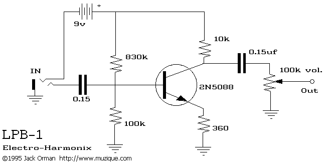
lpb1.gif


I need some guidance on going on to connect them on my board, after thats done and I have made some mods to suit me, we will make a real board inside a case and such (right now I'm using one of those spring-science fair project kits)

thanks a lot guys. :toast:
 
Dude ask your dad, I would have to ask my dad (also an electrical engineer) on how to read that. Or use this Wiki article

EDIT: Some more symbols than wikipedia has Here
 
would the battery be connected to the 830 ohm and 10k resistor? ( I think thats right)

or would the 830 be connected to the 10k?

oh and where do I connect all the grounds to?


My father lives and breathes this stuff but I wanna try it myself.
 
would the battery be connected to the 830 ohm and 10k resistor? ( I think thats right).

Yes

or would the 830 be connected to the 10k?.

Yes, well they are connected together and then to the battery.

oh and where do I connect all the grounds to?.
The grounds are connected together or to the CASE.
The Ground on the Jack connects everything to the electrical ground of the Guitar.

My father lives and breathes this stuff but I wanna try it myself.

Yeah, have fun showing him you can do it!!:toast:
 
Last edited:
does it matter which way I connect the resistor to?

because they are not polarized components.

Like that 10k to the transistor collector, does it matter which way the resistor is?
 
does it matter which way I connect the resistor to?

because they are not polarized components.

Like that 10k to the transistor collector, does it matter which way the resistor is?

No, it does not matter; Like you said "non-polarized".:toast:
 
now I need to learn about ICs.
 
is the transistor connected to the second (closest to the right) capacitor? or just the resistor is, or both?

thanks, I am breaking out of my n00b shell.
 
Transistor: Look at the flat part (face the flat part that has the part number toward you), the lead on the LEFT is 1, middle is 2, right is 3.

Lead 1: other side of 10k on battery, .15uF#1+(if its polarized, some caps are not)
Middle lead: other side of 830k on battery, 100k, .15uF#2
Lead 3: 360
 
You can call it an emitter, collecter and base, they are more..."exact". & I am not THAT much of a n00b!

Thanks.
 
LOL'z

I was reading it back thinking I should have put a :toast: in there somewhere...its getting late and I forget words on a screen can't convey tone (but a smiley can :p)

what are you using for a board? I saw a program somewhere that can lay out the best places to put components if you draw the schematic...

lol don't burn yerself (i like yelling - ow molten lead is hot!)
:toast:
 
I am prototyping on on of them "x in one" spring project kits, then I do any mods/alterations then we are probably gonna drill & etch, we got special etching ferric chloride and a paper that you iron on the board, good stuff.

I do know how to solder well though. Weller FTW!

My solder got the tin and resin inside it as well, lead is just for the neuro-toxicity and low melting point.
 
Ok I got it done, my father is gonna look it over, add the finishing touches and begin testing.
 
Back
Top