• Welcome to TechPowerUp Forums, Guest! Please check out our forum guidelines for info related to our community.

The 12V-2x6 Connectors Appear to Handle Full Load While Partially Inserted

So it seems improved metallurgy of the connector pins is the answer. I wonder if the same metallurgy in the older 12VHPWR connector would benefit as well.
 
Soooo...

As it happens, I've begun to research crimping for my electronics Hobby. I was immediately hit with $500 to $2000 crimpers, with huge OEM warnings about "cables will not be to spec if you do not use the OEM cimper". Apparently, wires and crimping are seriously complex. OEMs are supposed to do a good job with these dies, but the mechanical engineers think very deeply about how the internal strands of wire (and you're only supposed to use stranded wire), at the appropriate gauge (26 gauge has its own cap vs 22 gauge) will be squeezed and properly form a vacuum seal when the crimper does its thing.

Furthermore, it is well known that a bunch of cheapos will often try to save money by buying cheaper $100 or $200 crimpers that are not up to spec, leading to weaker connections in practice.


-----------

At this point of the 2x6 saga, I'm more than willing to blame the crimper as opposed to the connection itself. There's a huge amount of complexity in the crimp, copper characteristics, pins, etc. etc. that could go wrong. There have been enough tests done with "proper cables" (which likely also had proper crimps), showing an ability to handle full loads. But somehow, one way or the other, bad crimps likely got in the way (ex: a little pocket of air got in between the strands of copper, meaning the amp-rating was worse than expected, meaning when at full load the thing will catch on fire)

Any crimp will catch on fire in this manner if done poorly. But you're supposed to use expensive and highly-rated tools to prevent this problem. But maybe those expensive tools had a failure rate (0.01%) or maybe the technician in charge of crimping had a bad day and did something poorly (didn't apply pressure, misaligned a crimp, etc. etc.) and failed to see the quality-problem before shipping it to the customer.

Since 12V powering a 800W GPU is something like 66 Amps of current, meaning each strand of a 2x6 cable is taking ~11 Amps, we are absolutely operating at the "edge" cases of what crimpers are capable of. Crimpers are the highest-quality electrical connection you can make with stranded wire (even more reliable than soldering), but even crimpers have their limits. The M20 pin (popular for hobbyist) crimpers that handle 2-amps in my field are already $500 each (and thus hobbyists often use non-OEM crimpers but derate our crimps severely), I can't imagine the level of engineering to reliably create 10-Amp crimps at this miniature size. Any small mistake will almost certainly lead to overheating when we're talking about 11-Amps per damn copper cable.
 
Last edited:
It's a TEST. How hard is that to understand? They've clearly set things up to test the cables and connectors, since that's what the company manufactures.
This is NOT a real world behaviour.
You've clearly never been involved in making anything if you don't understand this.
I KNOW its a TEST, but they left out the bit with what the SENSE PINS are supposed to DO !
 
I KNOW its a TEST, but they left out the bit with what the SENSE PINS are supposed to DO !
You clearly don't get it, so no point discussing this with you.

So it seems improved metallurgy of the connector pins is the answer. I wonder if the same metallurgy in the older 12VHPWR connector would benefit as well.
Not just that, but how it interfaces with the pins on the GPU side as well.
There were two types of connector manufacturers for the 12VHPWR stuff, one good, one not good.

Soooo...

As it happens, I've begun to research crimping for my electronics Hobby. I was immediately hit with $500 to $2000 crimpers, with huge OEM warnings about "cables will not be to spec if you do not use the OEM cimper". Apparently, wires and crimping are seriously complex. OEMs are supposed to do a good job with these dies, but the mechanical engineers think very deeply about how the internal strands of wire (and you're only supposed to use stranded wire), at the appropriate gauge (26 gauge has its own cap vs 22 gauge) will be squeezed and properly form a vacuum seal when the crimper does its thing.

Furthermore, it is well known that a bunch of cheapos will often try to save money by buying cheaper $100 or $200 crimpers that are not up to spec, leading to weaker connections in practice.


-----------

At this point of the 2x6 saga, I'm more than willing to blame the crimper as opposed to the connection itself. There's a huge amount of complexity in the crimp, copper characteristics, pins, etc. etc. that could go wrong. There have been enough tests done with "proper cables" (which likely also had proper crimps), showing an ability to handle full loads. But somehow, one way or the other, bad crimps likely got in the way (ex: a little pocket of air got in between the strands of copper, meaning the amp-rating was worse than expected, meaning when at full load the thing will catch on fire)

Any crimp will catch on fire in this manner if done poorly. But you're supposed to use expensive and highly-rated tools to prevent this problem. But maybe those expensive tools had a failure rate (0.01%) or maybe the technician in charge of crimping had a bad day and did something poorly (didn't apply pressure, misaligned a crimp, etc. etc.) and failed to see the quality-problem before shipping it to the customer.

Since 12V powering a 800W GPU is something like 66 Amps of current, meaning each strand of a 2x6 cable is taking ~11 Amps, we are absolutely operating at the "edge" cases of what crimpers are capable of. Crimpers are the highest-quality electrical connection you can make with stranded wire (even more reliable than soldering), but even crimpers have their limits. The M20 pin (popular for hobbyist) crimpers that handle 2-amps in my field are already $500 each (and thus hobbyists often use non-OEM crimpers but derate our crimps severely), I can't imagine the level of engineering to reliably create 10-Amp crimps at this miniature size. Any small mistake will almost certainly lead to overheating when we're talking about 11-Amps per damn copper cable.
It's already been verified that it was one of the two connector manufacturers that was the issue due to not enough surface contact.
 
I KNOW its a TEST, but they left out the bit with what the SENSE PINS are supposed to DO !
That's intentional. They are intentionally inducing a worst case scenario. It passed.
 
It's already been verified that it was one of the two connector manufacturers that was the issue due to not enough surface contact.

Weird.

I thought it was NVidia connectors that were catching on fire?

I'm glad to see Intel taking precautions, but were there ever problems with the 12vhpwr connector on Intel GPUs?
 
That's intentional. They are intentionally inducing a worst case scenario. It passed.
Just to emphasise this point. Apparently they bridged out the sense pins to force an out of spec situation so they could really push the power pins.
 
Weird.

I thought it was NVidia connectors that were catching on fire?

I'm glad to see Intel taking precautions, but were there ever problems with the 12vhpwr connector on Intel GPUs?
Intel is the original author of both specs, people just credit nvidia for the fact its been exclusive to their cards thus far.
 
Intel is the original author of both specs, people just credit nvidia for the fact its been exclusive to their cards thus far.

Hmmm. Now that I know more about the peculiarities of crimping, I feel like (internet) researching this problem again. I never realized how much engineering went into crimps (and/or how easily a newbie engineer could cause widespread fires by making the wrong crimps).

When NVidia 12vhpwr problems were occurring last year or whenever, do you remember who supplied the power-cables? Was that from NVidia or was that from the power-supply companies?

------------

Like, these pictures of "melting connectors" is literally the same picture of melted plastic / fire hazards (albeit with these NVidia connectors rather than the other proprietary connectors). Somehow I never made the connection until now that crimps may be everything to this puzzle...
 
Last edited:
Hmmm. Now that I know more about the peculiarities of crimping, I feel like (internet) researching this problem again. I never realized how much engineering went into crimps (and/or how easily a newbie engineer could cause widespread fires by making the wrong crimps).

When NVidia 12vhpwr problems were occurring last year or whenever, do you remember who supplied the power-cables? Was that from NVidia or was that from the power-supply companies?
Astron and some other group (NTK?) assembled the cables, that's all I know. Astron ones were considered problematic, the other group ok, last I checked.
 
Last edited:
Astron and some other group (NTK?) assembled the cables, that's all I know. Astron ones were considered problematic, the other group ok, last I checked.

Thanks.

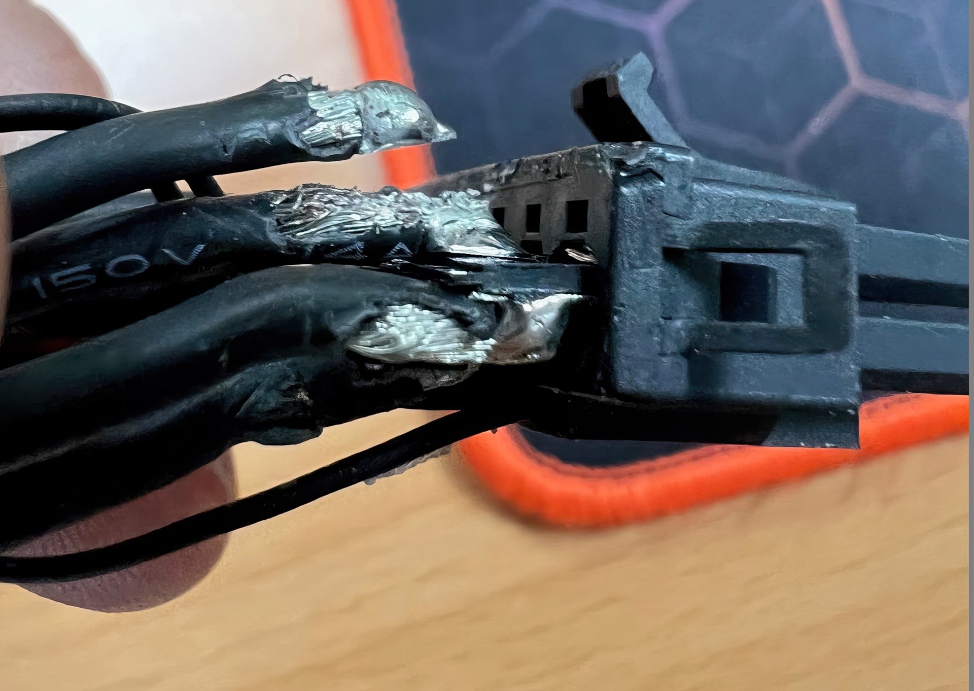
Meanwhile, as Igor's Lab points out, Astron's 12VHPWR adapter has its thick 14AWG wires rigidly soldered to 2mm^2 soldered pads, which is a point of failure, especially for contacts on the edges of the adapter.

Oh gosh. Soldered?

Well... okay then. There's your problem. Solder is made out of rigid tin and could crack-bend-and-change. You crimp because the copper wire fuses due to the flexibility of copper, creating the most reliable connection. Solder, especially when moving around due to users like, moving... will bend and break. It may come out 1.5 mOhms or better out of the factory, but that will change (in ways that copper can flex-and-retain its capabilities... while tin-based solder will bend and break). Especially these days as we're removing the flexible metal "lead" from our solder...


1695692831943.png


This is it IMO. You shouldn't solder connectors, they should be crimped instead.

-----------

Bonus points: the solder is going to be wicked up those wires and make the copper-wires more brittle as well.

This is absolutely 100% the smoking gun. I didn't realize that Igor's Lab figured this out a year ago. Then again, I didn't have the knowledge of crimps vs solder like I do today, so even if it was figured out before, I wasn't smart enough to recognize the answer to this mystery. Here I was assuming it was related to a bad crimp job, but the answer is even worse. Astron's wires weren't even using crimping to begin with, but a far worse methodology (soldering) instead.
 
Last edited:
Intel is the original author of both specs, people just credit nvidia for the fact its been exclusive to their cards thus far.
Not really.
The original 12VHPWR came from PCI-SIG, and Nvidia is one of the board members of PCI-SIG.
Intel just happened to include it inside the ATX 3.0 spec in Feb 2022.
But Nvidia was using the '12 pin connector' in the 3000 series since since 2020, and the 'NOT 12VHPWR' connector in 3090Ti.
Way ahead of the Intel ATX 3.0 spec announcement.

So it is Nvidia from start to end.
 
So you make a revision to a standard to allow something pulling +600W to work when partially inserted?
Shouldn't the revision avoid partiall insertion in the first place?
Safety.

Things need to fail in a safe way, and sometimes it's as simple as making sure the power delivery and ground pins are in a certain order.
 
That's not exactly safety in the technical sense. What it is is just reliable operation.

Safety is a human life risk equation. So the safety risk would be of burning down the building. There is a non-zero risk of that but not really what is being discussed here.
 
This is it IMO. You shouldn't solder connectors, they should be crimped instead.
Soldered joints aren't universally worse than crimped joints. They can't withstand repeated mechanical stress but if they are secured (inside an enclosed connector etc.), they are reliable. But the example in the pic is beyond horrible, for reasons that you described well.

I haven't worked with lead-free solder but old-style Sn63/Pb37 solder is brittle enough, and pure lead is brittle too, you can flex a piece of lead a few times, then it will break.

At this point of the 2x6 saga, I'm more than willing to blame the crimper as opposed to the connection itself. There's a huge amount of complexity in the crimp, copper characteristics, pins, etc. etc. that could go wrong.
Maybe ... but the design, manufacturing, and quality control of male and female pins are complex, too. The pins have to withstand elevated temperatures, temperature cycling, mating cycles, sideways movement in all directions, some oxidation and more. Experts might be able to determine the point of failure from available photos. There are many (photos, not experts).
 
Soldered joints aren't universally worse than crimped joints. They can't withstand repeated mechanical stress but if they are secured (inside an enclosed connector etc.), they are reliable. But the example in the pic is beyond horrible, for reasons that you described well.

Fair. Solder is cheaper and lower-tech (you don't need a $2000 crimping die matched per gauge of wire). Solder can be visually inspected while crimping is much more difficult to inspect / analyze if its high quality (the pressures of the copper strands are all internal to the crimp, so you're very much relying upon the crimp tool-die and manufacturing pressure to work).

I probably should say: solder is inferior for this particular **point** of the 12vhpwr connector. This location is going to see the highest levels of mechanical stress in typical usage, because dumb users who don't know any better will often yank, pull, or push upon that location. And the wires clearly have no strain-relief.

1695736986256.png


Lol @strain relief (or... lack of strain-relief) over the internal soldered joint. This is... horrifying... from a connector perspective. They're seriously running 600W+ over this?
 
The notable impact here is everything that already has 12VHPWR plugs is now defunct. ATX v3.0 is dead. I'll be avoiding buying any power supply that has a 12VHPWR plug.
 
Last edited:
Which intel... is the author of? Also the connector is an even older Molex part (MiniFit line IIRC), before all this.

So it is Nvidia from start to end.
Not sure that's being honest about how it went down. They drove it to be adopted, at most.
 
Also the connector is an even older Molex part (MiniFit line IIRC), before all this.
It's called Micro-Fit 3.0 and was introduced in 2017. How do I know? I follow TECHP⏻WERUP! Hey, and you do too - see your comment there.
3.0 appears to be the pin pitch here, not version.
 
It's called Micro-Fit 3.0 and was introduced in 2017. How do I know? I follow TECHP⏻WERUP! Hey, and you do too - see your comment there.
3.0 appears to be the pin pitch here, not version.
If people see my post count and think I don't REALLY follow this site, they really think I have a lot more time on my hands than I do. Honestly I spend way too much time here, enough so that I basically neglect any other social media presence, lol.
 
Is the change on the GPU and PSU side only? Or does the plug have any changes?

Pretty much all the melts I have seen have been due to CableMod 90-degree connectors, etc.
Hell, some dude even melted his 8-pin on a RTX 4070 a couple of weeks ago, lol.
 
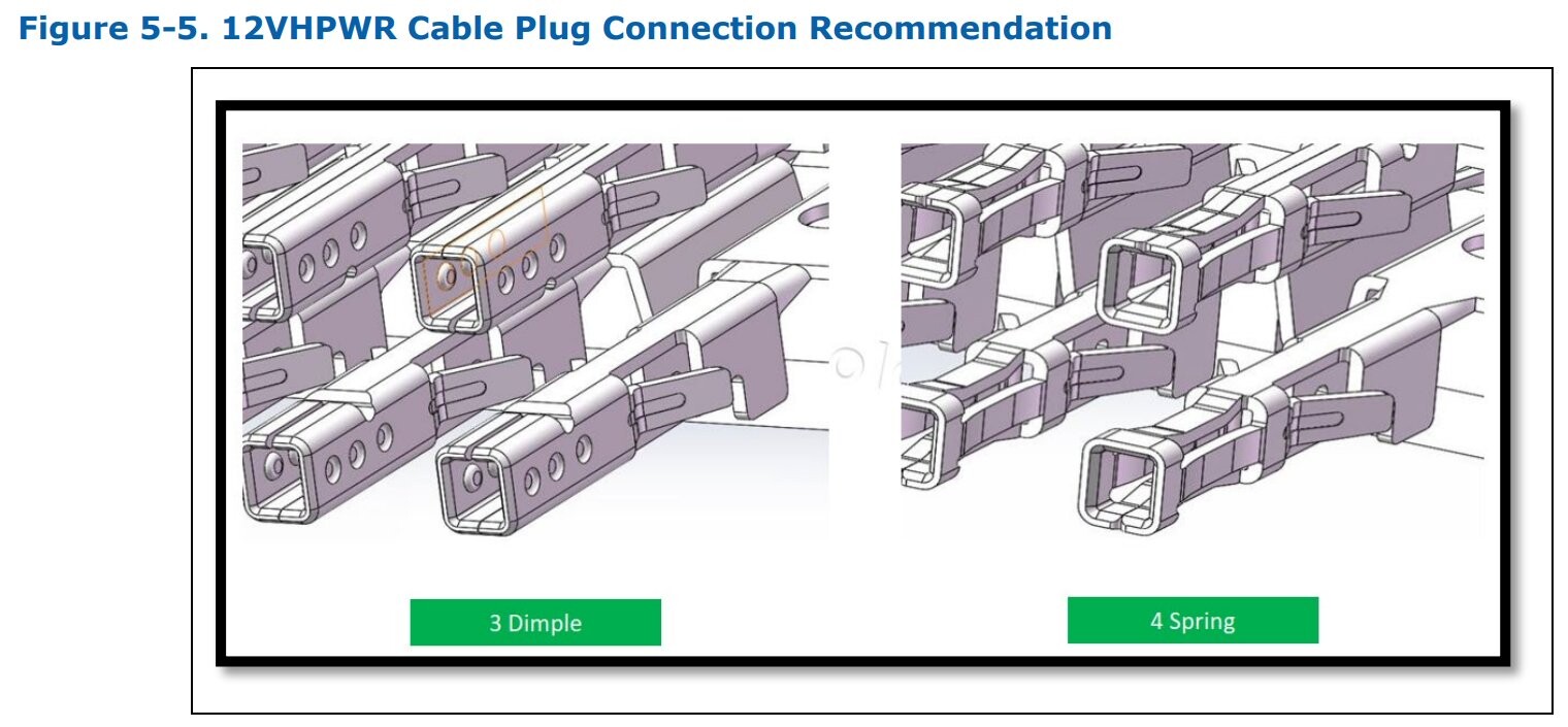
Read the article dude! It's all about the plug. Specifically the pins inside the plug were never up to the job. Basically a bad choice by the ATX 3.0 spec.

Really should be a full on recall of all affected products by all manufactures of ATX v3.0 power supplies at the very least. They've sold something that isn't fit for purpose.
 
I don't get the purpose of another connector. I don't even get get the purpose of the PCIe connectors when we have the EPS12V. I've run 300W through it for hours on end. It locks into place firmly. I struggle to get it off the motherboard. No need for those sense pins.
 
I don't get the purpose of another connector. I don't even get get the purpose of the PCIe connectors when we have the EPS12V. I've run 300W through it for hours on end. It locks into place firmly. I struggle to get it off the motherboard. No need for those sense pins.

Well for one, EPS12V is only rated for 336W while this 12v 2x6 is rated for over 600W.

Some modern computers have 600W GPUs on them. Instead of running two 300W cables to feed it, it makes more sense to design a new connector that can handle 600W instead.
 
He has a point. Why did the 6-pin and 8-pin GPU connectors even come into existence? The answer likely has nothing to do with capacity of the connectors but more about separation of use. Maybe to prevent inappropriate use, or to allow power supply designers more flexibility about internal partitioning.
 
Back
Top