• Welcome to TechPowerUp Forums, Guest! Please check out our forum guidelines for info related to our community.

ThrottleStop Only Applying CPU Core Offset, NOT CPU Cache Offset

Joined
Jan 29, 2024
Messages
6 (0.07/day)
System Name Alienware m15 R1 Windows 11 Pro
Processor Core-i7 8750H
Motherboard 0900DH Intel HM370 (Cannon Lake-H)
Cooling Stock (used on multi-fan cooling pad)
Memory 32GB DDR4-2666
Video Card(s) NVIDIA RTX 2060, 6GB GDDR6
Storage OS: Force MP510 960GB NVMe, Data: Intel SSDPEKNW020T8 2TB NVMe
Display(s) Built-in: AU Optronics FHD, Aux1: Dell P2314T FHD, Aux2: HP W2071d
My setup is Alienware m15 R1, Core-i7 8750H CPU, 32GB DDR4, RTX-2060 GPU, Win 11 Pro, UEFI firmware v2.19.0, ThrottleStop 9.6

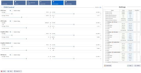
I can check Unlock Adjustable Voltage in ThrottleStop and enter voltage offsets in all five areas of FIVR control, but two of them are NOT applied by TS (CPU Cache and System Agent). CPU core applies instantly and shows up in the FIVR table, but CPU Cache always shows 0.0 offset and “default” in the voltage column. I am not planning to offset parameters other than CPU Core & CPU Cache, but I checked the other settings after discovering the issue with CPU Cache. Intel GPU and iGPU Unslice are applied and show up in the FIVR table like CPU Core, but System Agent shows up the same as CPU Cache, 0.0 offset and “default” in the voltage column. I also checked with a program that does the same thing as TS (QuickCPU) and it shows the same as TS for CPU Core and CPU Cache. I attached screenshots of 1-TS FIVR settings, 2-TS core temps during TS Bench, and 3-QuickCPU FIVR Control (showing same as TS).

ThrottleStop Prerequisites: Just prior to installing TS I had opened my laptop and thoroughly cleaned the dust from the two fans and all the heatsink fins, so it is currently clean inside. I worked all weekend unlocking my BIOS, as the fix that seemed to work for most folks (grub EFI shell to unlock the CFG & OC variables) did not work for me, apparently because I have two VarStores named “Setup” and the locks were in the second one. It was a lot of frustration and effort but I did get the firmware locks changed using RU.efi/RU.exe. Then, despite disabling/uninstalling all virtualization-related modules in Windows settings, disabling Virtualization-based Security via RegEdit, and turning off Memory Integrity/Core Isolation, I had difficulty getting VBS to show as disabled in SystemInfo; it always came up running. Finally, I found a CLI command (bcdedit /set hypervisorlaunchtype off) that did the trick, so I was then able to unlock adjustable voltage parameters in ThrottleStop FIVR. After turning off Secure Boot Mode to do the firmware unlocks, I had to turn it back on in order to boot my laptop again.

One other question: Three of the six cores (always the same three) run hotter than the other three. The three hot cores will always hit 100C (within less than 60sec of clearing max values) during “normal” laptop use (no gaming). I noticed while running TS Bench that the three hot cores were 94-100 while the three cooler cores were 61-65, with all cores showing the same C0% at 99+. Could there be a reasonable explanation for this other than the need to re-paste my CPU? THANK YOU for any insights!
 

Attachments

  • 1-TS FIVR 2024-01-29.jpg
    1-TS FIVR 2024-01-29.jpg
    382.9 KB · Views: 125
  • 2-TS Bench Running 2024-01-29.jpg
    2-TS Bench Running 2024-01-29.jpg
    150.1 KB · Views: 116
  • 3-QuickCPU FIVR Control 2024-01-29.jpg
    3-QuickCPU FIVR Control 2024-01-29.jpg
    233.5 KB · Views: 108

unclewebb

ThrottleStop & RealTemp Author
Joined
Jun 1, 2008
Messages
7,357 (1.27/day)
Exit ThrottleStop, delete the ThrottleStop.INI configuration file and reboot. That should fix the cache offset not being applied problem.

A 35C difference in max core temperatures when equally loaded is either a heatsink that is not flat or the thermal paste has pumped out. Honeywell PTM 7950 cold be your new friend. Lots of laptop owners have trouble with MX-4.
 
Joined
Jan 29, 2024
Messages
6 (0.07/day)
System Name Alienware m15 R1 Windows 11 Pro
Processor Core-i7 8750H
Motherboard 0900DH Intel HM370 (Cannon Lake-H)
Cooling Stock (used on multi-fan cooling pad)
Memory 32GB DDR4-2666
Video Card(s) NVIDIA RTX 2060, 6GB GDDR6
Storage OS: Force MP510 960GB NVMe, Data: Intel SSDPEKNW020T8 2TB NVMe
Display(s) Built-in: AU Optronics FHD, Aux1: Dell P2314T FHD, Aux2: HP W2071d
THANK YOU!!! I thought I had tried that already, but it must have been before I had all the other configuration parameters correct.

The first time I restarted, I did so from the Start Menu-->Restart and there was no change. Then, as I was taking a screen snip to post back, it hit me that I had read "restart" will not clear the data, that I had to do a full shutdown, then power back up. That did it, thanks very much!

I took a quick look at PTM7950 and the consensus seems to be very positive. I'm a little nervous about removing the heat-sinks, heat-pipes, fans, and motherboard. Especially the thin flex cables that don't seat very well and always seem to have that blue transparent tape on them to hold the flex in the board connector. I had a lot of difficulty in an Asus laptop with the monitor video flex cable and couldn't get it to stay in the connector well enough to make all the pin contacts after I removed/reinstalled the motherboard. But the fan noise has become almost non-stop (and I don't game at all), so I guess I don't have much choice. Cleaning the dust out of everything definitely helped, but it still doesn't take much more than idle to get the fans going on high, and one of them has developed a noisy bearing when running at high speed, making it hard to concentrate.

Anyway, I'll play with the ThrottleStop settings first and see how much that helps, then probably read up on doing the PTM7950 thermal solution and go ahead with it. I have to echo the comments I have read from others; I commend your amazing attentiveness to this forum and the lengths you go to help anyone/everyone who posts a question or has an issue, and I can't thank you enough for your super-fast reply. I should have thought to try that again with the INI file. I appreciate your help!

P.S.-I just noticed that you posted a link to the VBS issue (or perhaps that's part of your sig?). I actually followed ALL the methods outlined in that article, but my VBS was still running until I found the command line solution. No idea why the beebom.com methods didn't work for me, something was VBS very persistent on my machine. Thanks again!
 
Last edited:

unclewebb

ThrottleStop & RealTemp Author
Joined
Jun 1, 2008
Messages
7,357 (1.27/day)
something was VBS very persistent on my machine
Some computers have a virtualization option in the BIOS that also needs to be disabled. It might be called something like VT-x.

I have never done any in depth analysis of all the VBS things that might prevent ThrottleStop from working correctly. The beebom link in my signature does not solve the VBS issue for everybody but at least it points people in the general direction. Glad to hear that you were able to solve your problem.
 
Joined
Jan 29, 2024
Messages
6 (0.07/day)
System Name Alienware m15 R1 Windows 11 Pro
Processor Core-i7 8750H
Motherboard 0900DH Intel HM370 (Cannon Lake-H)
Cooling Stock (used on multi-fan cooling pad)
Memory 32GB DDR4-2666
Video Card(s) NVIDIA RTX 2060, 6GB GDDR6
Storage OS: Force MP510 960GB NVMe, Data: Intel SSDPEKNW020T8 2TB NVMe
Display(s) Built-in: AU Optronics FHD, Aux1: Dell P2314T FHD, Aux2: HP W2071d
From what I have seen, you do a whole lot more than “point people in the general direction”, but your modesty is appreciated. Every single system is unique, thus there is no solution for anything that will work for everyone.

Regarding replacing my CPU/GPU thermal paste w/ PTM7950, when I do that, do you recommend re-using the existing thermal pads on the surrounding under-heatsink components? Some folks recommend replacing them with thermal putty or new thermal pads, but some say just to leave them alone. What are your thoughts on this?

My laptop is almost 5 years old but as I mentioned I do not game (never have, no plans to do so). But with TS undervolting active as shown in the FIVR screen snip (with IccMax for CPU Core & CPU Cache at 150.0, and no values set or modified by XTU), my system enters thermal throttling instantly upon launching any kind of test and remains throttling for the entire duration of the test. This includes the shortest TS Bench, XTU CPU Stress Test, benchmarks, etc.

XTU CPU test throttles with Max Core Freq hovering around 3 GHz and a package power of 35-36W. Also, with nothing running except TS/XTU, launching Firefox will result in thermal throttle, albeit only for several seconds. In all cases the thermal throttle appears due to the hot cores, while the cool cores get nowhere near 100C. The attached XTU graph shows a 3 min. CPU Stress Test with AVX2 followed by a 120M TS Bench, and at the end of the graph you can see a throttling condition with low CPU utilization caused by a Firefox launch.

Thanks for your insights, only when you get a chance; I know you have a lot of people wanting to tap your knowledge!
 

Attachments

  • TS Main+FIVR Table During TS Bench 2024-02-01 101020.jpg
    TS Main+FIVR Table During TS Bench 2024-02-01 101020.jpg
    162.3 KB · Views: 39
  • XTU ST-TS Bench-FF Launch 2024-02-01 101605.jpg
    XTU ST-TS Bench-FF Launch 2024-02-01 101605.jpg
    156 KB · Views: 39

unclewebb

ThrottleStop & RealTemp Author
Joined
Jun 1, 2008
Messages
7,357 (1.27/day)
When the cores are equally loaded while running the TS Bench test, you should never be seeing core to core temperature differences of 35°C to 40°C.

1706811301859.png


What are your thoughts on this?
I have never looked inside an Alienware laptop. I do not know if the thermal pads that Dell uses are going to fall apart. All I know is that your core to core temperatures are horrible. Undervolting is not enough to solve the cooling problem that your laptop has. Either the heatsink is not flat or the thermal paste has failed and some of it has pumped out. Here is an example of what happens when a thermal paste fails.


dc_IV

New Member
Joined
Dec 30, 2023
Messages
17 (0.14/day)
...
Regarding replacing my CPU/GPU thermal paste w/ PTM7950, when I do that, do you recommend re-using the existing thermal pads on the surrounding under-heatsink components?
...
They also have PTM7950 sheets, that you can cut to the existing pad size, and then those are fresh too.
 
Joined
Jan 29, 2024
Messages
6 (0.07/day)
System Name Alienware m15 R1 Windows 11 Pro
Processor Core-i7 8750H
Motherboard 0900DH Intel HM370 (Cannon Lake-H)
Cooling Stock (used on multi-fan cooling pad)
Memory 32GB DDR4-2666
Video Card(s) NVIDIA RTX 2060, 6GB GDDR6
Storage OS: Force MP510 960GB NVMe, Data: Intel SSDPEKNW020T8 2TB NVMe
Display(s) Built-in: AU Optronics FHD, Aux1: Dell P2314T FHD, Aux2: HP W2071d
Success! After replacing the factory paste with PTM-7950 my situation is MUCH better, thank you so much for the help and for pointing me in the right direction. Fortunately, the AW m15 is about as easy as it gets regarding heat-sink removal, so I lucked out there. I attached a PDF summarizing my results in the form of several pages of screenshots in case it is of interest to others. I really wasn’t sure exactly how to document the performance (as far as what is of interest to this community), or what exact data to gather, since I’m not a gamer, but I took a crack at it. Note that the graphs in the PDF are at 50%, so in Acrobat or Adobe Reader you can zoom the document to 200% and still get full resolution to better see the info.

When I get a chance, I plan to take a more detailed look at the data I gathered as it relates to performance and thermals, in hopes of continuing the learning process. I already learned a lot, but as with most things technical, the more you learn, the more you realize you don’t know. Thank you again unclewebb for sharing your insights and knowledge, I very much appreciate the time you took to reply to my questions!
 

Attachments

  • RTm15 Post-PTM7950 Summary Observations Feb 2024.pdf
    1.9 MB · Views: 46
Joined
Sep 11, 2023
Messages
54 (0.23/day)
Success! After replacing the factory paste with PTM-7950 my situation is MUCH better
Thanks, congrats, superb results! Since you have had a PTM 7950 could you please share some photos with its package and labels. I'm asking that because market is flooded with fakes these days, yours' genuine for sure.
 
Joined
Dec 18, 2023
Messages
169 (1.27/day)
Thanks, congrats, superb results! Since you have had a PTM 7950 could you please share some photos with its package and labels. I'm asking that because market is flooded with fakes these days, yours' genuine for sure.
Are there also fakes in Russia?
Unclewebb could distribute the originals.:D
 
Joined
Jan 29, 2024
Messages
6 (0.07/day)
System Name Alienware m15 R1 Windows 11 Pro
Processor Core-i7 8750H
Motherboard 0900DH Intel HM370 (Cannon Lake-H)
Cooling Stock (used on multi-fan cooling pad)
Memory 32GB DDR4-2666
Video Card(s) NVIDIA RTX 2060, 6GB GDDR6
Storage OS: Force MP510 960GB NVMe, Data: Intel SSDPEKNW020T8 2TB NVMe
Display(s) Built-in: AU Optronics FHD, Aux1: Dell P2314T FHD, Aux2: HP W2071d
Here is more info on the PTM7950 (and thermal pad) I purchased, as well as a brief summary of the process from the perspective of one who had previously never done this type of work on a laptop. The results weren’t perfect, but I was coming from a condition of really horrible, awful, no good thermal cooling, so I am very satisfied with the results. Thanks unclewebb for suggesting the PTM-7950!

Attached photos with notes:
  1. PTM7950 Amazon listing & pics.
    • URL: https://www.amazon.com/PTM7950-40x80x0-2mm-JOYJOM-Conductive-Silicone/dp/B0BRJB8JNX/
    • I included the bottom two images in this pic because I initially thought that the actual PTM material itself had not been sent. But the PTM material is not shipped inside the plastic bag; it is between two protective pieces of cardboard the same size as the bottom of the box. They were turned with the label facing down (left), whereas I might have noticed it sooner if the label was facing up (right). The reason I mention this is that while researching the PTM7950 I came across a post with the OP showing the same baggie of accessories and complaining that he did not receive the PTM material at all. After initially thinking the same thing, I thought perhaps others might also overlook the cardboard protectors.
  2. Factory TIM on CPU & heatsink.
    • This is the first time I have pulled the heatsink assembly in a laptop so I have no reference, but it looked like the TIM was not sufficiently distributed over the die (but it did have 5 years of nearly 24/7 runtime).
  3. Factory TIM on CPU, GPU, & heatsinks.
    • It appears that in Dell’s assembly process they use some sort of PTM, as both the dies and especially the heatsinks look as if they originally had rectangular “pads” applied, before the processors heated up and melted the material in contact with the dies.
  4. Dies and heatsinks cleaned and ready for PTM7950.
  5. PTM-7950 cut and ready for application to dies.
  6. PTM-7950 applied (from front).
    • In this and the next pic you can see I messed up the edges a little when trying to remove the first plastic backing from the PTM. I did that trying to use a small, pointed pair of tweezers, then an exacto-knife with a new blade (I went ahead with it as shown in the pics). All the tips/videos I came across used one of these methods to separate the protective plastic from the first side (side that goes against the die).
    • For me, it was much easier and caused less damage to use two of the green tabs stuck to the plastic backing on opposite sides on the PTM and pull the tabs in opposite directions. Whichever one started coming off first, that’s the side I removed first, using the remaining tab to position the PTM without touching its surface. Then I used the tab to remove the remaining plastic backing once I had the PTM in place.
  7. PTM-7950 applied (from back).
    • It kind of looks like the CPU is not completely covered in one corner, the one that looks rounded. But that is actually just the epoxy potting adhesive peeking out; the CPU die itself is completely covered.
  8. Original thermal pad that I replaced.
    • I noticed there was a very thick thermal pad in close proximity to the CPU that had a lot of “excess compression” (very deep indentations) for the four chips it covered. The pad may very well be that thick intentionally so that it would also contact the lower-height resistors right next to each chip, but I don’t know enough about the function/operation of each component to further evaluate the situation (so I guess the smart thing to do would have been to leave it alone!). However, given the extreme uneven CPU cooling I was getting, almost 40 C between lowest and highest max-core-temps when evenly loaded during TS Bench, I decided to replace the pictured pad with the next size down. I estimated the original pad to be 1.5mm, so I replaced this pad with a 1.0mm pad to make sure it wasn’t affecting the heat-sink contact with the CPU die. More experienced folks may or may not agree with this decision, but at this point I am not inclined to experiment with various different pad thicknesses.
  9. New thermal pad that I applied.
Hope this helps!
 

Attachments

  • 01-PTM7950 Amazon.jpg
    01-PTM7950 Amazon.jpg
    286.1 KB · Views: 42
  • 02-RTm15 CPU Factory TIM.jpg
    02-RTm15 CPU Factory TIM.jpg
    1.4 MB · Views: 46
  • 03-RTm15 CPU GPU Factory TIM.jpg
    03-RTm15 CPU GPU Factory TIM.jpg
    710 KB · Views: 44
  • 04-PTM7950 ready to apply.jpg
    04-PTM7950 ready to apply.jpg
    1.7 MB · Views: 44
  • 05-PTM7950 check cut.jpg
    05-PTM7950 check cut.jpg
    1.7 MB · Views: 43
  • 06-PTM7950 Applied (front).jpg
    06-PTM7950 Applied (front).jpg
    2 MB · Views: 38
  • 07-PTM7950 Applied (back).jpg
    07-PTM7950 Applied (back).jpg
    4.3 MB · Views: 37
  • 08-Replaced Thermal Pad.jpg
    08-Replaced Thermal Pad.jpg
    213.6 KB · Views: 42
  • 09-Replacement Thermal Pad.jpg
    09-Replacement Thermal Pad.jpg
    652.3 KB · Views: 40
Joined
Sep 11, 2023
Messages
54 (0.23/day)
Last edited:
Joined
Dec 18, 2023
Messages
169 (1.27/day)
8.5 W/mK is a very poor thermal conductivity.
Silicon 851 Thermal Grease has a conductivity of 13.4 W/mK.
 
Joined
Sep 11, 2023
Messages
54 (0.23/day)
This is not about conductivity, besides all these numbers are made from some internal (in-house) tests under conditions we do not know for sure.
 
Last edited:
Joined
Sep 11, 2023
Messages
54 (0.23/day)
And what is it about?
We are talking about notebooks here. Desktop PCs or external full-size GPUs are not concerned. But if we do i should say that even having not ideal conditions and cooling system with some defects, they will anyway feel better with regular thermal pads or whatever. But not when you deal with notebooks! They have got shared cooling system which efficiency could depend even from 1 degree trends or direct sun lights.

Shortly, one of the main reasons is quality and tightness of clamp of cooling system (plate containing heat sinks, fans, pipes etc). Well known example of that bad implementation was Lenovo Legion 5 (or 5 Pro) of last editions. Manufacturer just used less screws which brought to gap under certain clamp. It is just one example, there are a lot of others even nowdays.

The other advantage of a "liquid" thermal pads is ability to fill up gaps and levelling the curvature of cooling system itself or some of its components.
 
Last edited:
Joined
Dec 18, 2023
Messages
169 (1.27/day)
Unfortunately, liquid pastes, apart from liquid metal, have poor thermal conductivity, so they are not suitable for high-performance laptops.
 
Joined
Sep 11, 2023
Messages
54 (0.23/day)
Unfortunately, liquid pastes,
It is not what you mean "liquid". This one can be spreaded and formed much more better and convenient compared to common thermal pads with predefined thickness.
 
Joined
Dec 5, 2019
Messages
57 (0.04/day)
I have noticed that most systems nowdays only apply cache, unslice and system agent voltage offsets, moving the CPU and GPU sliders shows on throttlestop but doesn't crash ever - nor produce any change in wattage and frequency. That is after using efi shell to unlock cfg and overclock lock and VBS is totally disable. They also behave the same on macos with voltageshift.
 

unclewebb

ThrottleStop & RealTemp Author
Joined
Jun 1, 2008
Messages
7,357 (1.27/day)
moving the CPU and GPU sliders shows on throttlestop but doesn't crash ever
On most CPUs you have to adjust both the Core and Cache equally. If you only adjust the core, it might not do anything.

Same thing goes for the Intel GPU and iGPU Unslice. Adjust these two equally if you want them to work. Moving only the Intel GPU slider will not do anything unless the iGPU Unslice is also adjusted. Post a screenshot of your FIVR settings if you are having any problems.

most systems nowdays
Since the FIVR first existed way back starting with 4th Gen CPUs, you have always had to adjust the voltages in tandem.
 
Joined
Dec 5, 2019
Messages
57 (0.04/day)
On most CPUs you have to adjust both the Core and Cache equally. If you only adjust the core, it might not do anything.

Same thing goes for the Intel GPU and iGPU Unslice. Adjust these two equally if you want them to work. Moving only the Intel GPU slider will not do anything unless the iGPU Unslice is also adjusted. Post a screenshot of your FIVR settings if you are having any problems.


Since the FIVR first existed way back starting with 4th Gen CPUs, you have always had to adjust the voltages in tandem.
I have MSI systems of every generation where i can easily adjust them with different values and see them crashing with like -170 on core and -80 on cache; i did many skylake/kabylake systems with different values back then. That is how i know that on average the CPU takes a lot more undervolt on skylake compare to the cache, while on Haswell they were usually very close.
 
Joined
Dec 5, 2019
Messages
57 (0.04/day)
just an update: i can say for sure on Zbook G3 with old 2019 bios, the core and cache voltage offsets are indeed working indipendently, if i launch TS with clear config and apply -250 to core, system crashes, and the optimal setting is -160 core and just -110 cache

On DELL gen 8 and newer, the core and cache are indeed tied - it will only apply the lowest value, i can set -250 to core or -250 to cache and that does nothing until i also set the other to a proper value (usually around 100 wich i guess is the cache limit)
 
Top