A Detailed Look Into PSUs |
|
Main Switches – Transformer
The main switches operate in two modes only, ON (fully conduction) and OFF (fully non-conduction) and chop the DC signal, coming from the smoothing capacitor, into pulses whose amplitude is the magnitude of the input voltage and whose duty cycle is controlled by a switching regulator controller (Marty Brown – Power Supply Cookbook). Thus the DC signal is converted to an AC rectangular waveform that is fed to the transformer. The latter steps down the voltage which feeds the secondary rectifiers that generate all DC outputs (+12V, 5V, 3.3V, 5VSB, -12V). The transformer also plays the role of an isolator between the primary and the secondary side.
When the switches are ON there is zero voltage across them (theoretically) and when they are OFF we have zero current through them. So always the product V × I is zero. This means that there is no power loss on the switches. However this represents an ideal situation and in real life there are power losses since there is no transistor/MOSFET than can switch instantly. There is always a small period that a transistor (switch) is between ON and OFF state (also called linear region) and during this period the V × I product is not zero. Because of that all MOSFETs in a PSU (and not only) are cooled down by heatsinks and a fan (although there are some PSUs that use only passive cooling).
Output Rectifiers and Filters

The roles of output rectifiers and filters are, as their names state, to rectify and filter the high frequency switching waveform created by the switches (MOSFETs) and fed through the secondary of the main transformer(s). In this stage we meet two types of rectification designs, passive and synchronous. In the first Schottky Barrier Rectifiers (SBRs) are used and in the latter MOSFETs take the place of SBRs. In synchronous rectification efficiency is increased since we get rid of the forward voltage drops of SBRs. To make this crystal clear let's give an example. A typical SBR has 0.5V voltage drop so if we want to conduct 40A then we have 40 × 0.5 = 20W. Now if we use a MOSFET instead of an SBR and assuming that the MOSFET's RDS(on) is 3 mO then we have 40 × 40 × 0.003 = 4.8W. This results in 15.2W less power dissipation and 24% increase in efficiency.
Besides the two above designs sometimes a hybrid one, called semi-synchronous design, may be used. In semi-synchronous MOSFETs and SBRs are used to reduce cost and increase the efficiency above passive design's levels.
The generation of -12V is done with the usage of a conventional diode, since we do not demand much power from this rail (below 1A in most cases). For 5VSB a completely independent circuit with a transformer is usually used, since 5VSB are working continuously even when the PSU is OFF (in standby mode). For the generation/filtering of the main outputs (+12V, 5V and 3.3V) there are three types of regulation. Group regulation, independent regulation and DC-DC conversion. We will analyze each one of them in the below paragraphs.

Group regulation is usually used in low capacity PSUs and budget ones. A fast way to identify group regulation is by checking the number of coils used in the secondary side. If you find only two then group regulation is present. The bigger coil is used for 12V/5V and the smaller one for 3.3V. In this regulation type +12V and 5V are generated together and both of them feed back their output voltage error to the regulator controller. This means that if the load is unbalanced between the rails, then the regulator controller has a really hard time to properly implement regulation (e.g. if the load at +12V is high and at 5V is low then the voltage on the second rail will be raised because the regulator controller tries to raise the +12 rail voltage, but since the latter is connected to 5V then both of them are raised.) This is why most group regulated PSUs fail to keep their rails within +/-5% tolerance at Crossload tests. In group regulation the 3.3V rail is usually regulated by a mag-amp post-regulator from 5V or from 12V (scarcely).

Independent regulation is used in higher capacity and performance PSUs where cost comes in second place. In this type of regulation all main DC outputs have their independent regulation circuit and unbalanced loads do not cause problems to the rails' voltages. The +12V rail is regulated by the main regulator controller and 5V/3.3V by mag-amp post-regulators. You can easily indentify a PSU that uses independent regulation by the number of toroidal coils in its secondary side. If you find three of them (one for each rail) then the PSU uses independent regulation.
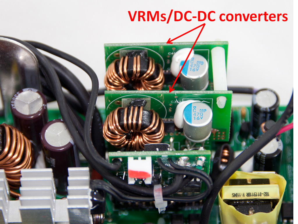
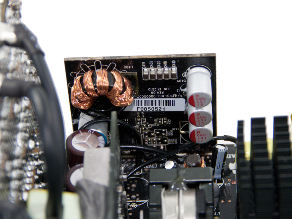
Now in many contemporary PSUs the generation of the minor rails is done with the use of buck -step down- converters (DC-DC converters or Voltage Regulation Modules – VRMs). In these PSUs 5V/3.3V are generated from the +12V directly. This has a positive impact on efficiency and in cross-regulation. Here we must note, PSUs that utilize DC-DC conversion are independent regulated too.

A last note before we move to the next stage, the toroidal chokes located after the rectifiers take part not only in the rectification but also in the filtering process, since they are used for ripple, voltage and current, reduction on the DC outputs. However in PSUs that utilize LLC resonant topologies usually there are no toroidal chokes in the secondary (for +12V generation) and if there is any then it is used only for filtering.
Aug 1st, 2025 21:26 CDT
change timezone
Latest GPU Drivers
New Forum Posts
- 9800x3d apart from gaming (21)
- Ubiquiti Networks users!!! (2)
- Free Games Thread (4836)
- memory used for store firmware in adapters wifi usb (2)
- Inside a wifi antenna (0)
- ASUS SBW-06D2X-U BR Drive not being detected in Linux (0)
- Technical Issues - TPU Main Site & Forum (2025) (295)
- The Official Thermal Interface Material thread (1814)
- What's your latest tech purchase? (24425)
- My UPS keep sending alarm when I game (37)
Popular Reviews
- ASUS ROG Crosshair X870E Apex Review
- MSI Claw 8 AI+ A2VM Review
- Montech X5 Review
- Orbital Pathfinder Review
- Herman Miller Logitech G Embody Review - No Pain, No Gain
- Lenovo Legion 5i (15IRX10) Review - Feature-Rich and Wallet Friendly
- Upcoming Hardware Launches 2025 (Updated May 2025)
- Lian Li HydroShift II LCD-C 360TL Review
- Noctua NF-A12x25 G2 PWM Fan Review
- Lian Li O11 Dynamic Mini V2 Review
TPU on YouTube
Controversial News Posts
- AMD's Upcoming UDNA / RDNA 5 GPU Could Feature 96 CUs and 384-bit Memory Bus (137)
- AMD Radeon RX 9070 XT Gains 9% Performance at 1440p with Latest Driver, Beats RTX 5070 Ti (131)
- Intel "Nova Lake-S" Core Ultra 3, Ultra 5, Ultra 7, and Ultra 9 Core Configurations Surface (110)
- DDR6 Memory Arrives in 2027 with 8,800-17,600 MT/s Speeds (102)
- NVIDIA to Debut GeForce RTX 50-series SUPER GPUs by Christmas (101)
- AMD Sampling Next-Gen Ryzen Desktop "Medusa Ridge," Sees Incremental IPC Upgrade, New cIOD (97)
- Intel CEO Confirms SMT To Return to Future CPUs (95)
- NVIDIA Becomes First Company Ever to Hit $4 Trillion Market-Cap (94)