Radeon X800 Pro/XT/XT PE Voltmods |
|
Using Variable Resistors
This section I decided will be brief due to time restraints and less descriptive. Understanding the same warnings as posted previously in the begining of the article. You should read the "Introduction" and "Before you Begin" sections.There are several VR How-Tos on the web. Each one has a different tweak, it's one of those more than one way to skin a cat deals. But we'll just do the basic VR to resistor solder.
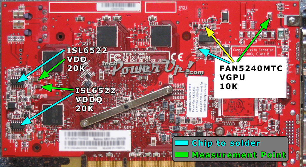
Image 4

Image 5

Image 6
Tools and Supplies
To do these mods you should aready have soldering skills and should be using a low wattage iron. I also assumed that you would be using a magnifying glass and until now didn't think to mention it.- Digital Multimeter (have to have one)
- Glue Gun (to set VR in place)
- Variable Resistors: 1x 10k Ohm, 1x 250k Ohm, 2x 20k Ohm
Next read the "Getting Started" section to get your default voltage. This can be important to get an idea of where your voltage will be when you crank up the card. You can still use the same table as the pencil mod. What I mean by that is if the default Ohm reading of the VGPU is at 420 and you add the 10k VR, then given that a 10k VR will give you around .04v which in turn equals 15 Ohms then after adding the VR your new Ohm reading should be around 405 Ohms.
VR VGPU
Locating the resistor R1597 in Image 5 you will use the 10k VR. Set the VR to 10k or as close to 10k as it will go using your mulitimeter. Check the resistance on R1597 to compare after you solder the VR. You can either solder the VR to the resistor directly or you can use wires. After soldering the VR on check the resistance. Remember a 10k VR should give you around 15 Ohms. Test your card and verify the voltage.VR IGPU Over Current Protection Vmod
Locate resistor R1596 in Image 5 and set your VR to 250k. Check the resistance on the resistor to compare after you solder the VR on. Again after soldering the VR on check the resistance. Like with the pencil mod you want to drop the resistence around 20k Ohms.VR VDD (VMem) Vmod
Using Image 6 we will solder a 20k VR to the pins 5 & 7 of the VDD chip. Set the resistor to 20k and check the resistance before then after. Test your card and verify the voltage.VR VDDQ Vmod
Same as the VDD vmod but on a different ISL6522CB chip below the VDD locate the VDDQ in Image 6. Just like the VDD set the VR to 20k and check the resistance before then after. Test your card and verify the voltage.
Apr 16th, 2024 19:00 EDT
change timezone
Latest GPU Drivers
New Forum Posts
- Help with troubleshooting rx 6800 xt (gigabyte master type c) (0)
- Is there any scientific reason airplanes don't get weighed before take off? (30)
- Will a RTX 4070 TI super bottleneck a Ryzen 9 7950X3D? (24)
- Asus 7 PIN fans to standard 4 pin PWM? (7)
- Battery swap for cyberpower UPS (39)
- Which air cooler for a ryzen 9 5900x (151)
- Are there RGB lit split keyboards? (6)
- Time to update the motherboards layout! (109)
- NVCleanInstall Error: Access to the path ”DisplayDriverExt.dll” is denied. (8)
- Strange behaviour with my i5 1235u HP laptop after Windows reinstall (12)
Popular Reviews
- Horizon Forbidden West Performance Benchmark Review - 30 GPUs Tested
- PowerColor Radeon RX 7900 GRE Hellhound Review
- Galax GeForce RTX 4070 Super EX Review
- Fractal Design Terra Review
- ASUS GeForce RTX 4090 Matrix Platinum Review - The RTX 4090 Ti
- Corsair 2000D Airflow Review
- Minisforum EliteMini UM780 XTX (AMD Ryzen 7 7840HS) Review
- Creative Pebble X Plus Review
- FiiO KB3 HiFi Mechanical Keyboard Review - Integrated DAC/Amp!
- ASUS GeForce RTX 4090 STRIX OC Review
Controversial News Posts
- NVIDIA Points Intel Raptor Lake CPU Users to Get Help from Intel Amid System Instability Issues (102)
- Sony PlayStation 5 Pro Specifications Confirmed, Console Arrives Before Holidays (99)
- US Government Wants Nuclear Plants to Offload AI Data Center Expansion (98)
- Developers of Outpost Infinity Siege Recommend Underclocking i9-13900K and i9-14900K for Stability on Machines with RTX 4090 (82)
- Windows 10 Security Updates to Cost $61 After 2025, $427 by 2028 (79)
- TechPowerUp Hiring: Reviewers Wanted for Motherboards, Laptops, Gaming Handhelds and Prebuilt Desktops (70)
- Intel Realizes the Only Way to Save x86 is to Democratize it, Reopens x86 IP Licensing (70)
- AMD Zen 5 Execution Engine Leaked, Features True 512-bit FPU (63)