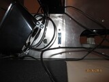
BUTLER P-47 (ROTATED MOTHERBOARD, SCRATCH BUILD, ALL IN ONE)


Owner:
Posted:
September 1st 2016
Updated:
Viewed:
4,227 times
Rating:
 8 votes total
Good (5.3)
Submit vote:
Please register on the forums & login to vote.
Key Features:


Worklog:
System Specs:
Performed Mods:
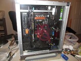
Scratch build from raw aluminum!
Front panel bent using bending tool.
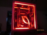
Primed and painted.
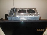
Gauges monitor voltage of intake and exhaust fans.
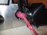
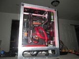
GPU sag eliminated by vertical orientation and support.
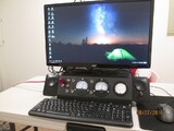
1. Angled aluminum front gauge panel.
2. Analog intake and exhaust fan voltage gauges.
3. Classic toggle switches.
4. Water cooling of CPU.
5. 90º MOBO rotation for uber air flow (intake fans on bottom, exhaust on top--no heat traps).
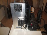
6. One cord to rule them all. No more laundry basket of components. Line power in box, with front panel toggle switch cutoff.
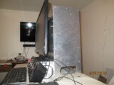
7. Speakers and monitor integrated on the case.
8. Power supply at the top of case, with no heat dumped inside.
Apr 27th, 2024 15:22 EDT
change timezone
Latest GPU Drivers
New Forum Posts
- Should I install Windows 10 or 11 for my new device (42)
- Ryzen Owners Zen Garden (7253)
- rx 6500 xt anisotropic filtering not working (5)
- RX 580 VBIOS related functionality not supported for Device: 0x67df (12)
- Usb 3.2 and usbc speeds became very slow (4)
- Best SSD for system drive (106)
- looking to build a new system and im considering asrock brand but i have some doubts/concerns. (21)
- Looking for recommendations to upgrade the GPU (12)
- Strange system crashes out of nowhere, help (17)
- What are you playing? (20548)
Popular Reviews
- Ugreen NASync DXP4800 Plus Review
- HYTE THICC Q60 240 mm AIO Review
- Upcoming Hardware Launches 2023 (Updated Feb 2024)
- MOONDROP x Crinacle DUSK In-Ear Monitors Review - The Last 5%
- Thermalright Phantom Spirit 120 EVO Review
- FiiO K19 Desktop DAC/Headphone Amplifier Review
- AMD Ryzen 7 7800X3D Review - The Best Gaming CPU
- Alienware Pro Wireless Gaming Keyboard Review
- ASUS Radeon RX 7900 GRE TUF OC Review
- Gigabyte GeForce RTX 4070 Ti Super Gaming OC Review
Controversial News Posts
- Windows 11 Now Officially Adware as Microsoft Embeds Ads in the Start Menu (139)
- Sony PlayStation 5 Pro Specifications Confirmed, Console Arrives Before Holidays (117)
- NVIDIA Points Intel Raptor Lake CPU Users to Get Help from Intel Amid System Instability Issues (106)
- AMD "Strix Halo" Zen 5 Mobile Processor Pictured: Chiplet-based, Uses 256-bit LPDDR5X (103)
- US Government Wants Nuclear Plants to Offload AI Data Center Expansion (98)
- AMD's RDNA 4 GPUs Could Stick with 18 Gbps GDDR6 Memory (95)
- Developers of Outpost Infinity Siege Recommend Underclocking i9-13900K and i9-14900K for Stability on Machines with RTX 4090 (85)
- Windows 10 Security Updates to Cost $61 After 2025, $427 by 2028 (84)
6 Comments on BUTLER P-47 (ROTATED MOTHERBOARD, SCRATCH BUILD, ALL IN ONE)
It takes up too much desk space, and cable management is a bit sloppy.
With a few of the larger components relocated the case could be a lot thinner allowing more desk top space for your use.
1. Use external angle framing, which would allow the PSU to be oriented "flat" and not conflict with the frame or create a large gap.
2. Watercool the GPU and use a PCI slot extender to allow it to lie parallel to the mobo.
3. The next build will be going for a different look, so the gauges will be digital and more compact.
Many PSU locations were tested out in the solid model, most either required a different frame structure or violated my airflow mandate. Is the PSU the larger component of which you speak? Which component(s) would you have moved?
I think the thing I like the best about the build is the vertical GPU (no card sag!) and the internal mobo IO routing. I know this would drive many people crazy, but I had fun with the concept of minimal flow resistance (this will be better when I switch out the soft tubing for hard).
I had a similar thought, that an extender be used to rotate the GPU flat adjacent to the Motherboard and with such a large base, the PSU be relocated down there, and possible a concealed cavity, with a removable top, in the base below the monitor for hiding cables which could be routed through a small opening to allow routing to components externally.