 1
1
Cooler Master Silent Pro M2 850 W Review
Voltage Regulation & Efficiency »A Look Inside
Before reading this page we strongly suggest a look at this article, which will help you understand the internal components of a PSU better.


By the design, and especially by the large heat sinks with the long fins, we easily figured out the OEM of this unit is Enhance – a company which cooperates closely with CM. This platform utilizes an Active Clamp Reset Forward topology on the primary side, while on the secondary, a synchronous rectification design along with a group regulation scheme, is used. Definitely not cutting edge technology, but Silver efficiency isn't too demanding after all.

We will start the tour, as usual, in the internals from the transient filtering stage. This starts right behind the AC receptacle with two X and two Y caps and the rest of its components - two CM chokes, two X and two Y caps, along with an MOV (Metal Oxide Varistor) - on the main PCB. There is also a large thermistor and a relay to bypass it once the start-up phase finishes. The aforementioned thermistor provides protection against large inrush currents that can damage the components of the PSU.

The single bridge rectifier is bolted onto the primary heat sink. Unfortunately, its markings are at the adjacent to the heat sink side, so we couldn't read them without de-soldering the whole primary heat sink – a battle we didn’t want to fight.


In the APFC two IPP50R140CP fets are used along with an STTH15R06D boost diode. The hold-up caps are two parallel Matsushita/Panasonic (330μF each or 660μF combined, 420V, 105°C) ones.

This unit uses an Active Clamp Reset Forward (ACRF) topology to achieve higher efficiency without increasing the production cost. This topology is cheap to implement and provides loss-less switching to minimized energy dissipation. It, on the other hand, has a small issue with increased ripple and needs a good secondary filtering stage. The primary chopper is an IPP50R140CP fet and the reset switch is an FQPF3N80C fet.


The secondary side uses synchronous design - the +12V rail rectifies four IPP041N04N fets, while the secondary rails handle two pairs of AP72T03GP fets. The same heat sink also houses the 5VSB rectify diode, an MBR1060, which can handle up to 10 A of current. Finally, like in the primary heat sink, copper plates are used on this one as well. These copper plates provide better thermal conductivity than aluminum, while the latter provides higher heat release and is, of course, much cheaper than copper. CM combines the best aspects of both materials with this hybrid heat sink.


The two toroidal chokes on the secondary side indicate that a group regulation design is utilized instead of an independent one for each rail. This has negative effects with highly unbalanced loads among the rails (e.g. large load at +12V and a minimal one on the minors and the opposite). We also noticed two heat shrinks, on two fins of the secondary heat sink. One thermistor is used by the fan speed control module, while the other is exploited by the over temperature protection circuitry.


Except for the 5VSB circuit, which uses a Chemi-Con cap, all other caps of the secondary side are provided by Teapo and rated up to 105°C.
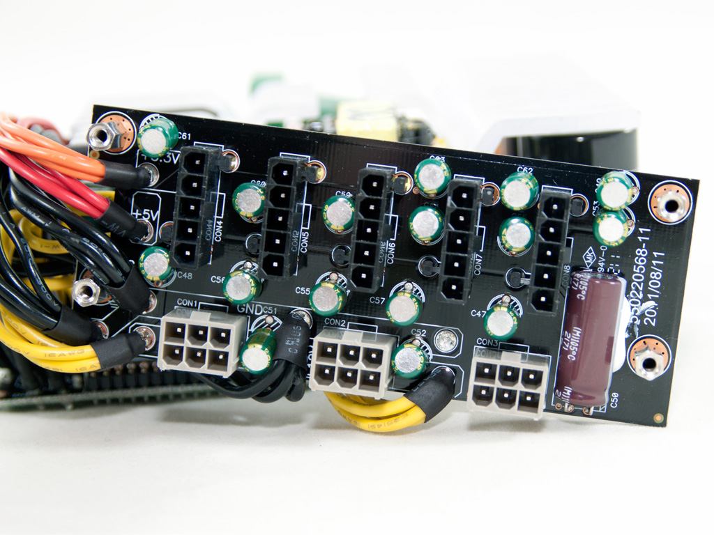


On the front of the modular PCB are many small Teapo filtering caps along with a bigger Chemi-Con one. On the rear side of the PCB, soldering quality is good and there are many SMD caps.


On the right side of this PCB the combo PFC/PWM controller, a Champion CM6802 IC, is installed. In this case it only controls the PFC converter since a UC2715D complementary switch FET driver controls the ACRF topology. In the middle of the PCB, we find two optocouplers, providing isolation between the two circuits. On the left side, the supervisor IC is installed - a SITI PS232S. The latter provides OCP for up to four +12V rails, something useless in this PSU since there is only one +12V rail. Also, this supervisor IC doesn't integrate OTP, but provides an additional protection input pin - the OTP signal passes through this pin to it.


Soldering quality on the main PCB is quite good, except for some areas of the secondary side where the manufacturer enhanced the earth traces in a rather sloppy way. We didn't spot any long component leads. We did find, on the secondary side, and under the +12V islands, three current shunts - an indication that this platform was initially designed to have three +12V virtual rails. In this case, all are shorted together to form a single one.

The cooling fan has Cooler Master's logo on it and its model number is DFS132512M (12V, 0.2 A, 2.4 W, 1500 RPM, 34.44 dBA, 78.13 CFM). At the bottom side of the center badge, we find its real manufacturer, which is Young Lin Tech. Similar to the M2 1000 W case, this fan isn't equipped with Hydro Dynamic Bearings (HDB,) but uses Hysint Bearings instead, which provide longer lifespan and lower noise than sleeve bearings. These bearings can't be compared with HDB/FDB ones, in terms of performance and lifespan. The latter are, however, much more expensive and used only in some high-end PSUs.
May 4th, 2024 03:02 EDT
change timezone
Latest GPU Drivers
New Forum Posts
- What's your latest tech purchase? (20426)
- NASA Achieves milestone Solid State Battery (221)
- Change GPU or PSU ? Games look cryspy and sharp with microsuttering (7)
- Alphacool CORE 1 CPU block - bulging with danger of splitting? (77)
- Outer Worlds getting boring (38)
- Old high quality PSU, or semi-old mid-quality PSU? (60)
- What are the consequences of genetically altering ticks, fleas, and mosquitoes to control their populations? (198)
- Keysfan (10)
- AM5 Motherboard Question, which of these two should I go with? (11)
- Asus Crosshair X670E - CPU Package temps (14)
Popular Reviews
- Finalmouse UltralightX Review
- Meze Audio LIRIC 2nd Generation Closed-Back Headphones Review
- ASRock NUC BOX-155H (Intel Core Ultra 7 155H) Review
- Montech Sky Two GX Review
- Gigabyte GeForce RTX 4070 Ti Super Gaming OC Review
- Upcoming Hardware Launches 2023 (Updated Feb 2024)
- HYTE THICC Q60 240 mm AIO Review
- Alienware Pro Wireless Gaming Keyboard Review
- Ugreen NASync DXP4800 Plus Review
- AMD Ryzen 7 7800X3D Review - The Best Gaming CPU
Controversial News Posts
- Intel Statement on Stability Issues: "Motherboard Makers to Blame" (236)
- Windows 11 Now Officially Adware as Microsoft Embeds Ads in the Start Menu (167)
- AMD to Redesign Ray Tracing Hardware on RDNA 4 (117)
- Sony PlayStation 5 Pro Specifications Confirmed, Console Arrives Before Holidays (117)
- AMD's RDNA 4 GPUs Could Stick with 18 Gbps GDDR6 Memory (114)
- NVIDIA Points Intel Raptor Lake CPU Users to Get Help from Intel Amid System Instability Issues (106)
- AMD "Strix Halo" Zen 5 Mobile Processor Pictured: Chiplet-based, Uses 256-bit LPDDR5X (103)
- AMD Ryzen 9 7900X3D Now at a Mouth-watering $329 (103)