 13
13
AirLive WMU-6500FS WiFi HDD & Downloader Review
Software & Initial Setup Wizard »A Closer Look

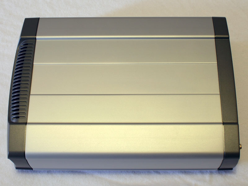
Both ends of the enclosure are made of plastic, while the body is made of aluminum. The overall structure of the WMU-6500FS is very sturdy, but still a bit larger than what you may be used to. You will find the AirLive logo on the top, while the bottom does not feature any writing or labels.
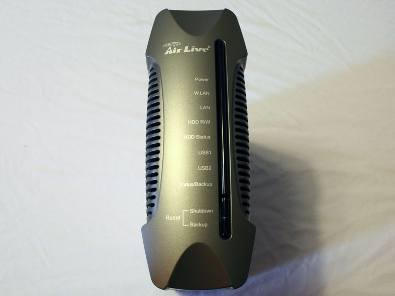

A long bar with green LEDs in the front of the device denote activity of the labeled functionality. There are two buttons on the bottom to reset, shut down or backup the enclosure. The back holds the female reverse SMA connector for the antenna, an Ethernet plug if you decide to use a cabled network, two USB 2.0 ports which can be used to connect further storage devices to the unit, an on/off switch and the power connector. The air vent is meant for a 4 cm fan, which is actually not included. The device does get quite hot after extended periods of operation, so you may want to place a fan inside the enclosure, if you plan to keep the WMU-6500FS on 24/7 in a less ventilated area.
Installation


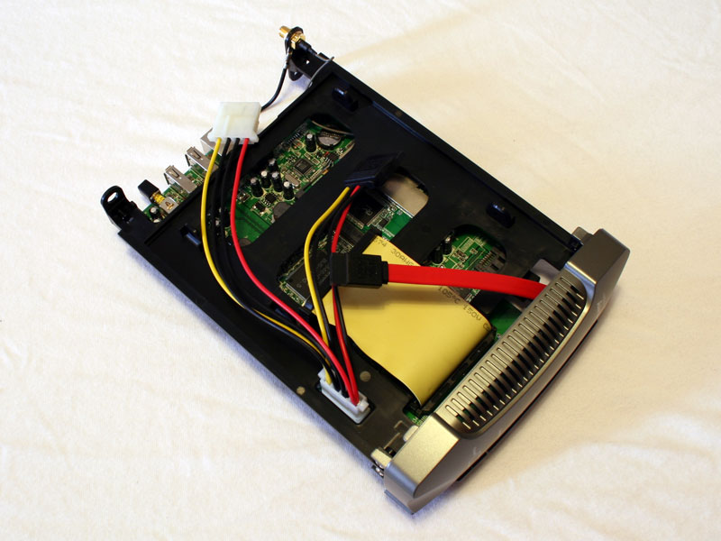
To gain access to the device, you simply need to remove two screws from the back of the enclosure. The front will then slide out easily. As you can see, the fan can easily be installed in the appropriate location. Even the PCB has been cut in the area of the rear fan, to give it enough space.

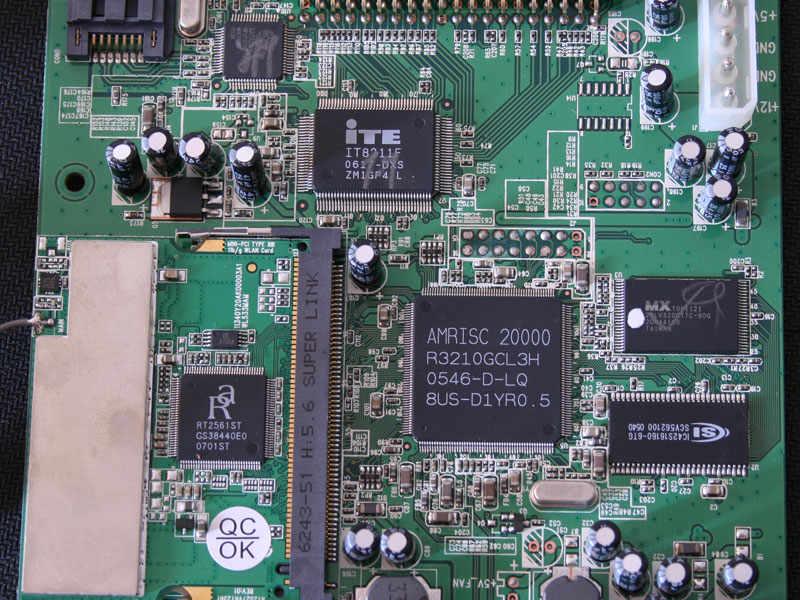
Speaking of which, the PCB is quite large and actually features a miniPCI slot for the 125 MBit/s Turbo-G. It should be mentioned that "Turbo-G" is not a standard. It is based on IEEE 802.11g which usually runs at 54MB/s maximum. To achieve such a speed, you usually need all other devices in your network to be of the same manufacturer using the same proprietary standard. This includes WiFi USB sticks, PCI cards and routers. The chip on the miniPCI WLAN card is the RaLink RT3651ST, which is an 802.11g chip.
Chips on the PCB:
- The large chip in the center of the PCB is the "NPU" A RISC processor with 133 MHz. For further reading on the RDC R3210G click here.
- The iTE IT8211F is the IDE controller, responsible for the IDE interface. To read up on this chip click here.
- The SATALink IC above the iTE chip is used to provide SATA connectivity.
- The IC42S16160 chip to the right of the risk processor runs at 166 MHz and is a 4MB x 16 Bit SDRAM IC.
- The MX 29LV320CTTC-90G above the SDRAM is a flash IC.

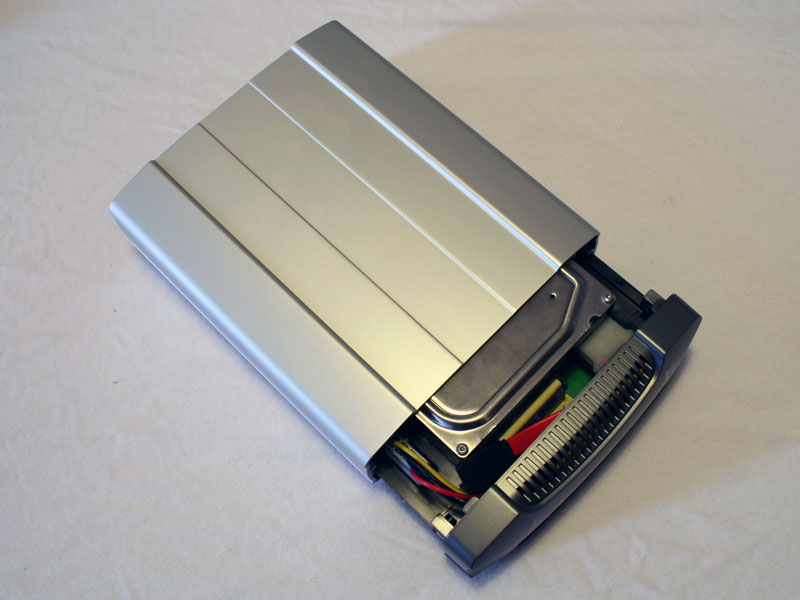
Installing the drive is very simple. In this case an IDE hard drive is used and considering the lack of USB 2.0 connectivity it does not really matter if you are using a 7200RPM or 5400RPM drive, as the bottleneck will be the Ethernet or WiFi connection. Once the drive is secured, simply slide the tray back into the aluminum casing and replace the two screws.
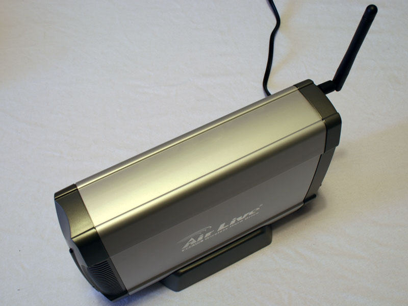
The last step includes screwing on the wireless antenna and connecting the power.
May 10th, 2024 19:54 EDT
change timezone
Latest GPU Drivers
New Forum Posts
- Going from a 2070 to a 4070 ti super, should i uninstall drivers first? (11)
- The Official Thermal Interface Material thread (1181)
- I don't think Ryzen 9900x3d is just being announced next month, I think it's launching next month. (26)
- AM5 boot times improve RADICALLY with memory context restore enabled (33)
- Intel Core Ultra 9 185H - PROCHOT (3)
- 6800XT Red Devil with 18°C difference from Core to Hotspot (13)
- Soundblaster x-ae5 plus sometimes switches center channel to other channels. (4)
- Arc OC'ing, anyone? (11)
- Flash VBIOS to turn RX 580 2048SP into RX 570 (34)
- NVME underperforming (2)
Popular Reviews
- CHERRY XTRFY M64 Pro Review
- Bykski CPU-XPR-C-I CPU Water Block Review - Amazing Value!
- ThundeRobot ML903 NearLink Review
- Corsair iCUE Link RX120 RGB 120 mm Fan Review
- Corsair MP700 Pro SE 4 TB Review
- ZMF Caldera Closed Planar Magnetic Headphones Review
- Upcoming Hardware Launches 2023 (Updated Feb 2024)
- Finalmouse UltralightX Review
- AMD Ryzen 7 7800X3D Review - The Best Gaming CPU
- Sapphire Radeon RX 7700 XT Pure Review
Controversial News Posts
- Intel Statement on Stability Issues: "Motherboard Makers to Blame" (264)
- AMD to Redesign Ray Tracing Hardware on RDNA 4 (206)
- Windows 11 Now Officially Adware as Microsoft Embeds Ads in the Start Menu (170)
- NVIDIA to Only Launch the Flagship GeForce RTX 5090 in 2024, Rest of the Series in 2025 (144)
- Sony PlayStation 5 Pro Specifications Confirmed, Console Arrives Before Holidays (119)
- AMD's RDNA 4 GPUs Could Stick with 18 Gbps GDDR6 Memory (114)
- NVIDIA Points Intel Raptor Lake CPU Users to Get Help from Intel Amid System Instability Issues (106)
- AMD Ryzen 9 7900X3D Now at a Mouth-watering $329 (104)