 4
4
Antec Basiq VP550P 550 W Review
Voltage Regulation & Efficiency »A Look Inside
Before reading this page we strongly suggest to take a look at this article, which will help you understand the internal components of a PSU much better.


The OEM of this little fellow is Delta Electronics, one of the largest and most experienced PSU manufacturers. Despite the underpopulated PCB we removed the bridge rectifier's heatsink along with the secondary side one, in order to give you a better view of the internals. Although we have a special de-soldering gun (Hakko 808) at our disposal, the removal of the secondary heatsink was really difficult.
The transient filter starts right at the AC receptacle with two Y caps. Also the two cables that transfer power to the main PCB are wrapped around a ferrite ring. On the main PCB there are more transient filtering components, namely two CM chokes and two pairs of X and Y caps. Unfortunately there is no MOV (Metal Oxide Varistor) present so the PSU is susceptible to spikes coming from the power grid, unless you use a surge protector with it.


The bridge rectifier, a T6KB60, can handle up to six Amps, so more than enough for the VP550P, taking also into account that it is attached to a dedicated heatsink. There is space for another parallel bridge rectifier on the PCB. After the bridge rectifier, the full wave rectified signal with 100 Hz frequency is filtered by the PFC input capacitor which in this case is an X one.


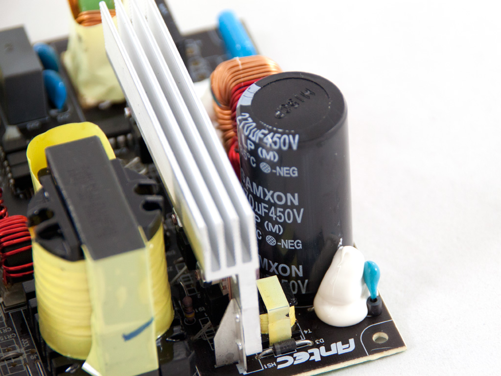
The APFC uses only one mosfet, since there is no need for voltage doubling as the PSU works only with 230VAC input and on top of that the max output power is small. An SPP21N50C3 mosfet is up to the task of separating the full wave rectified signal into constant pulse sequences. The hold cap is a Samxon labeled at 85°C and with 270μF capacitance. Thankfully, although it is only 85°C rated and doesn't come from the best available manufacturer it is rated at 450V, significantly higher than the APFC 380V DC bus voltage.

The main switches are two SPP15N60C3.


The combo PFC/PWM controller is the well known CM6800AG and is soldered on the main PCB. Also the standby PWM controller is a TNY278PN which can deliver up to 16W at 5VSB with 230VAC input.


In the secondary side only passive components are used. The +12V rail is handled by one STPS30L60CT and a pair of STPS20L60CT SBRs while 5V are generated from two MBR2045CT SBRs and 3.3V from one MBR3045 SBR. The presence of three toroidal chokes indicates that independent regulation is used for the generation of the rails, something that greatly affects, positively of course, cross load performance. To our surprise, since this is a real budget unit, all caps in the secondary are Japanese and provided by Rubycon, Nippon Chemi-Con and Nichicon with an 105°C rating. This sounds really weird but of course we are not going to complain about it!


The protection's IC, a DWA107, is soldered on a large daughter-board on the side of the main PCB.


Soldering quality on the main PCB is very good, typical of Delta platforms. On the solder side of the PCB we located the 5VSB rectifier, an SBR10U45.

The PCB indeed supports two +12V rails and the shunt resistors are located on the component side.

The cooling fan is provided by Yate Loon Electronics and its model number is D12SH-12. With a maximum speed of 2200 RPM and 40 dBA noise output you can't call it quiet, for sure.
Apr 25th, 2024 16:07 EDT
change timezone
Latest GPU Drivers
New Forum Posts
- What software are you using to monitor CPU temps during gaming session? (12)
- Alphacool CORE 1 CPU block - bulging with danger of splitting? (15)
- What are you playing? (20528)
- What phone you use as your daily driver? And, a discussion of them. (1480)
- Black screen after muting (4)
- Will a RTX 4070 TI super bottleneck a Ryzen 9 7950X3D? (59)
- How to check flatness of CPUs and coolers - INK and OPTICAL INTERFERENCE methods (111)
- Ghetto Mods (4321)
- Random blue screen from winload.efi error (0xc000000e) (2)
- Meta Horizon OS (20)
Popular Reviews
- Fractal Design Terra Review
- Thermalright Phantom Spirit 120 EVO Review
- Corsair 2000D Airflow Review
- Minisforum EliteMini UM780 XTX (AMD Ryzen 7 7840HS) Review
- ASUS GeForce RTX 4090 STRIX OC Review
- NVIDIA GeForce RTX 4090 Founders Edition Review - Impressive Performance
- ASUS GeForce RTX 4090 Matrix Platinum Review - The RTX 4090 Ti
- MSI GeForce RTX 4090 Suprim X Review
- MSI GeForce RTX 4090 Gaming X Trio Review
- Gigabyte GeForce RTX 4090 Gaming OC Review
Controversial News Posts
- Sony PlayStation 5 Pro Specifications Confirmed, Console Arrives Before Holidays (116)
- NVIDIA Points Intel Raptor Lake CPU Users to Get Help from Intel Amid System Instability Issues (106)
- Windows 11 Now Officially Adware as Microsoft Embeds Ads in the Start Menu (104)
- AMD "Strix Halo" Zen 5 Mobile Processor Pictured: Chiplet-based, Uses 256-bit LPDDR5X (101)
- US Government Wants Nuclear Plants to Offload AI Data Center Expansion (98)
- AMD's RDNA 4 GPUs Could Stick with 18 Gbps GDDR6 Memory (86)
- Developers of Outpost Infinity Siege Recommend Underclocking i9-13900K and i9-14900K for Stability on Machines with RTX 4090 (85)
- Windows 10 Security Updates to Cost $61 After 2025, $427 by 2028 (84)