 0
0
Cooler Master Silent Pro M2 1000 W Review
Voltage Regulation & Efficiency »A Look Inside
Before reading this page we strongly suggest to take a look at this article, which will help you understand the internal components of a PSU much better.


The OEM of this unit is Enhance Electronics and this is made quite obvious by the huge heatsinks with the extra long fins and mainly from the pair of black and white wires that feed the PCB with AC power. Usually these wires are brown and blue but Enhance has its own color codes, as it seems. The platform of this unit has many differences compared to the one of the Silent Pro Hybrid 1050W PSU and this is natural since the latter has Gold efficiency and is more expensive. To provide you a clear view of the internals we removed the two APFC caps and the secondary heatsink which fought well but eventually the Hakko 808 prevailed. These Enhance heatsinks are a real pain to remove and on top of that they totally block the view.

The first part of the transient filtering stage as usual starts right at the AC receptacle. In this case we found two X caps along with a pair of Y ones. Also the power cables are wrapped around a ferrite bead and the same applies to the grounding wire which is wrapped around a smaller ferrite bead. The second part of the transient filtering stage is located on the main PCB and includes two CM chokes, two pairs of X and Y caps and an MOV. Also next to the right CM choke resides a huge thermistor, for protection against large inrush currents and a little further there is a relay which cuts it off from the circuit once the start up phase finishes. This way it provides a small efficiency boost and the most important it allows the thermistor to cool down.

The two parallel bridge rectifiers are cooled by the primary heatsink and a smaller one. On the PCB there is room for a third bridge, for even more power.


Moving on to the APFC, we find a large PFC choke and in front of it the PFC input capacitor resides. This cap filters the high frequency ripple of the fully rectified signal, which derives from the output of the bridge rectifiers. The APFC uses two IPW60R099CP fets and an STTH15R06D boost diode. The hold up caps are two parallel Matsushita/Panasonic (390μF, 420V, 105°C).

This unit uses a two power switch Active Clamp Reset Forward (ACRF) topology to achieve higher efficiency. Recently Enhance heavily uses this topology in all of their higher efficiency PSUs, since it is cheap to implement and provides loss-less switching thus minimized energy dissipation. However it has a small issue with ripple suppression, at least in our experience. The primary choppers are two IPW60R099CP fets and the reset switch is an FQPF3N80C fet.


In the secondary side synchronous design is used and the presence of only two toroidal chokes means that a type of group regulation design is used for the generation of the main rails (12V, 5V and 3.3V). The +12V rail regulate four IPP041N04N while the minor rails handle two pairs of AP72T03GP. In the secondary heatsink the 5VSB SBR (MBR1060) is also bolted. This SBR can handle up to 10A so it will easily deliver the full power (3A) of this rail. Finally notice the copper plates on which all fets are installed. These provide better thermal conductivity than aluminium but the latter provides higher heat release and it is of course much cheaper than copper.

Almost all filtering caps used in the secondary are provided by Teapo and are rated at 105°C. Only the 5VSB converter is an exception to the above since it uses a Nippon Chemi-Con cap.


On the front of the modular PCB there are lots of small Teapo caps, which are used for extra filtering of the DC outputs from AC ripple. There is also a much larger Nippon filtering cap. On the rear side, soldering quality is good and we also found many SMD caps.


On the right side of the following large vertical PCB resides the combo PFC/PWM controller, most likely the CM6802S since its markings were fully erased, which in this case controls only the APFC circuit. On its left side the smaller IC is a UC2715D complementary switch FET driver, used by the ACRF topology. There is also a third IC on this side of the PCB, in the top right corner, which we couldn't recognize since it had no visible markings on it. In the middle of the PCB there are two opto-couplers which provide isolation between the two circuits and on the left side the supervisor IC is soldered, a PS232S. This IC provides OCP for up to four +12V rails, something not needed in this case since there is only one +12V rail and it doesn't integrate OTP, but provides an additional protection input pin so the OTP signal passes through this pin to the control IC.


Soldering quality on the main PCB is above average, that's for sure, but still isn't up to the levels that we are used to see from Enhance products. We spotted several hand made touch up jobs and some sloppy solder joints. Thankfully all component leads are short, meaning that the cutting guy did his job pretty well here. Finally we spotted five shunt resistors, three at the +12V area and two under the minor rails areas. The three shunts at +12V mean that this PSU initially had three +12V rails but Cooler Master preferred a single rail instead.


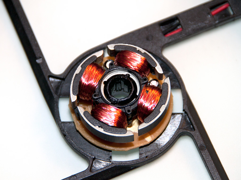


The cooling fan has Cooler Master's logo on it and its model number is DFS132512M (12V, 0.2A, 2.4W, 1500RPM, 34.44dBA, 78.13CFM). On the bottom side of the center badge we find its real manufacturer which of course is Young Lin Tech.
According to a spec sheet we found on Young Lin Tech's official site this fan is equipped with a plain sleeve bearing and not with a Hydro Dynamic one. On the contrary CM states that HDB is used, so we had to clear this up by cracking open the fan. In the end we discovered that the fan uses neither sleeve bearing nor HDB. The kind of bearing it uses is called Hysint bearing and is something in between. It provides longer lifespan and lower noise than sleeve bearing but it can't be compared with HDB/FDB. In the photos above notice the vertical V-shaped cutouts on the shaft of the fan. These curves pump the oil up and down on the bearing while the fan spins reducing friction. We contacted CM of course about this issue and they informed us that due to a patent on HDB/FDB each vendor has similar solutions with custom names, however there are also some differences in the design too.
May 6th, 2024 18:14 EDT
change timezone
Latest GPU Drivers
New Forum Posts
- Update on the whole PC rebooting issue. There was an extra standoff in the case, but now it's crashing even more (1)
- What's your latest tech purchase? (20449)
- Only some humans can see refresh rates faster than others, I am one of those humans. (185)
- Battery swap for cyberpower UPS (61)
- Silly question about upcoming CPU Upgrade (9)
- Gigabyte Aorus Elite AX V2 rev 1.1 BIOS update "AMD AGESA V2 1.2.0.B" (0)
- How can I improve my media serving setup? (1)
- Apparently Valve is giving refunds on Helldivers 2 regardless of hour count. Details inside. (106)
- GPU Hot Spot Temperature 105 Celsius, fans at 3000 RPM, while GPU Temperature is max 70 Celsius (39)
- 7900 XTX Seriously lacking (118)
Popular Reviews
- Finalmouse UltralightX Review
- ASRock NUC BOX-155H (Intel Core Ultra 7 155H) Review
- Meze Audio LIRIC 2nd Generation Closed-Back Headphones Review
- Cougar Hotrod Royal Gaming Chair Review
- Upcoming Hardware Launches 2023 (Updated Feb 2024)
- AMD Ryzen 7 7800X3D Review - The Best Gaming CPU
- Montech Sky Two GX Review
- ASUS Radeon RX 7900 GRE TUF OC Review
- HYTE THICC Q60 240 mm AIO Review
- Logitech G Pro X Superlight 2 Review - Updated with 4000 Hz Tested
Controversial News Posts
- Intel Statement on Stability Issues: "Motherboard Makers to Blame" (248)
- Windows 11 Now Officially Adware as Microsoft Embeds Ads in the Start Menu (167)
- AMD to Redesign Ray Tracing Hardware on RDNA 4 (165)
- Sony PlayStation 5 Pro Specifications Confirmed, Console Arrives Before Holidays (118)
- AMD's RDNA 4 GPUs Could Stick with 18 Gbps GDDR6 Memory (114)
- NVIDIA Points Intel Raptor Lake CPU Users to Get Help from Intel Amid System Instability Issues (106)
- AMD Ryzen 9 7900X3D Now at a Mouth-watering $329 (104)
- AMD "Strix Halo" Zen 5 Mobile Processor Pictured: Chiplet-based, Uses 256-bit LPDDR5X (103)