 12
12
Cooler Master V550S with 3D Circuit Design Review
Voltage Regulation, Hold-up Time & Inrush Current »A Look Inside & Component Analysis
Before reading this page, we strongly suggest a look at this article, which will help you understand the internal components of a PSU much better. Our main tool for the disassembly of the PSU is a Thermaltronics TMT-9000S soldering and rework station. It is of extreme quality and is equipped with a matching de-soldering gun. With such equipment in hand, breaking apart every PSU is like a walk in the park!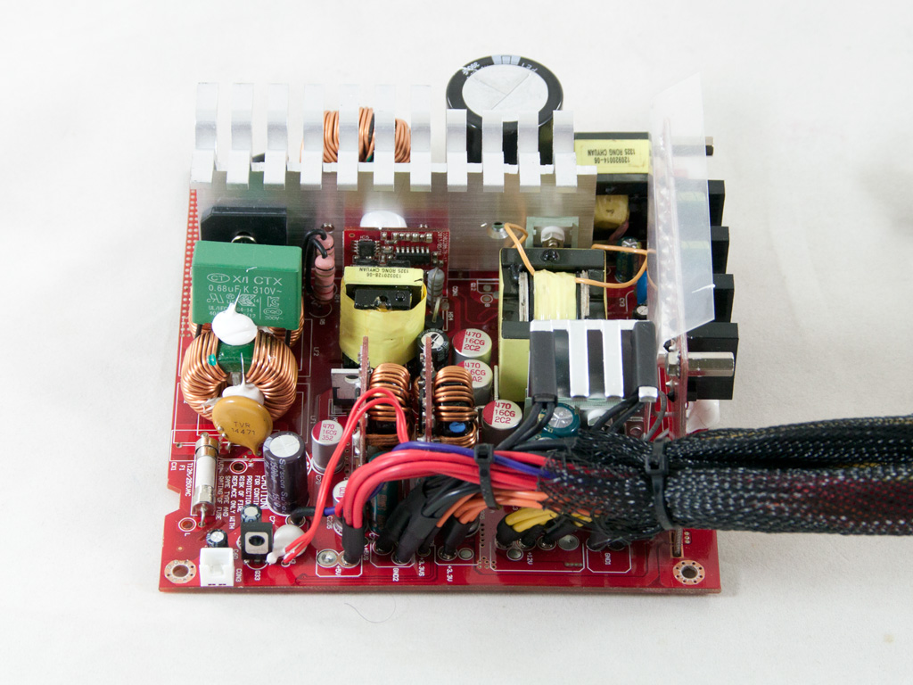
CM called upon their favorite OEM, Enhance, for these units, and Enhance does seem to have an ace up its sleeve with the 3D circuit design, or so it claims. A first look at the 3D design doesn't reveal anything special, but we will examine it closely shortly to figure out its particulars. The design of this platform is modern since an LLC resonant converter is used in the primary side and two small DC-DC converters generate the minor rails in the secondary side. Also, while the primary heatsink is quite large for a Gold unit, the secondary one is small.
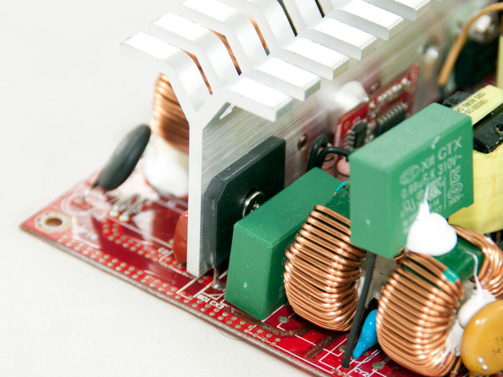
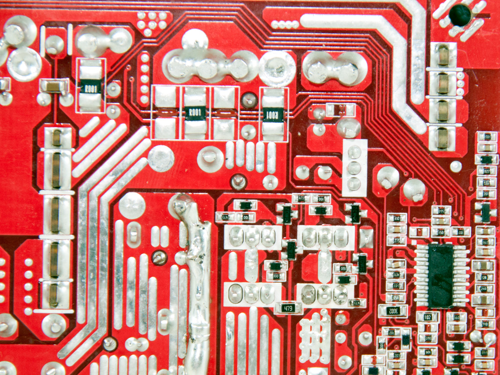
The transient filter starts at the AC receptacle with one X and two Y caps, and the power cables are wrapped around a ferrite ring for EMI suppression. On the main PCB are two CM chokes, a huge MOV, and two pairs of X and Y caps.
We couldn't identify the bridge rectifier since its markings are on the side that is in contact with the heatsink, and we weren't in a de-soldering mood.
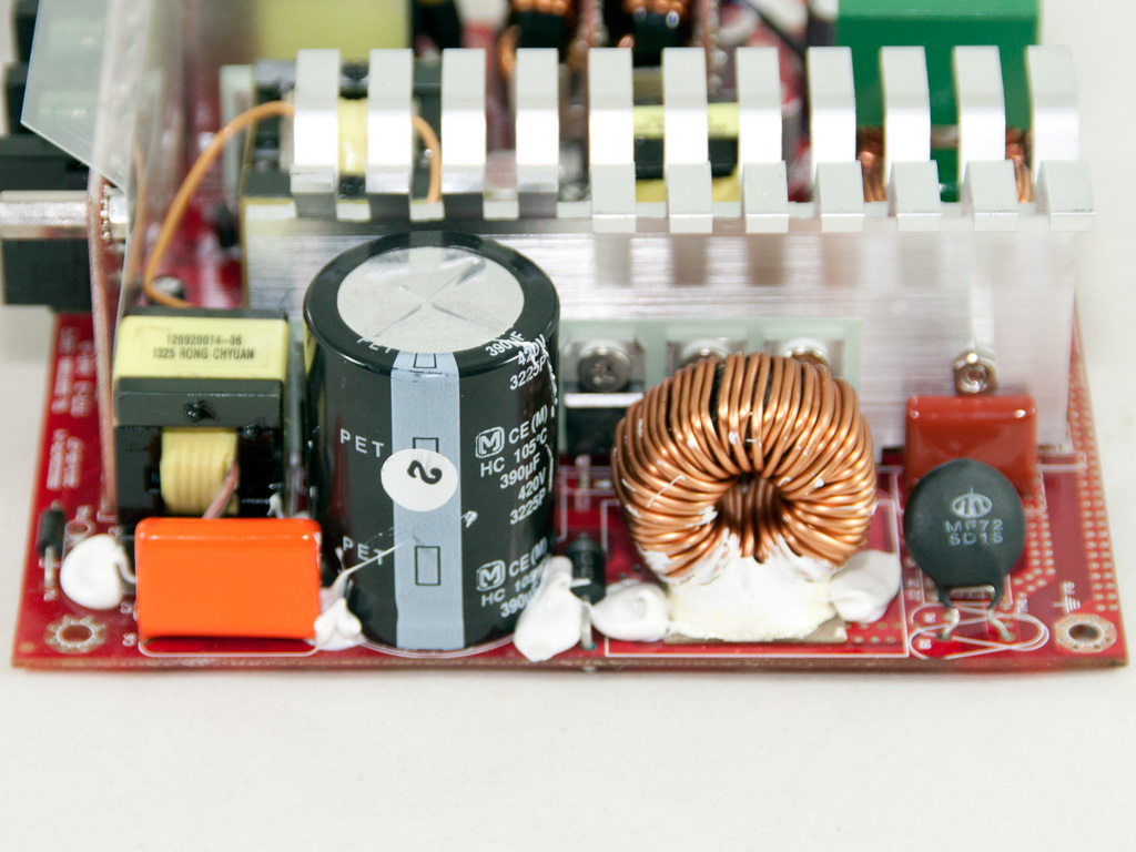
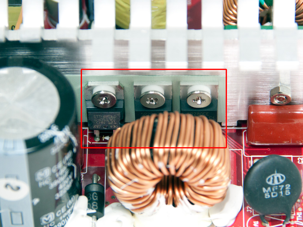
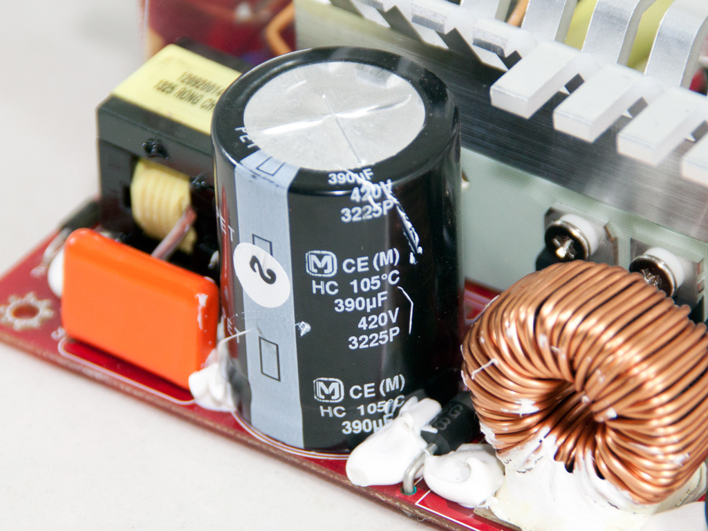
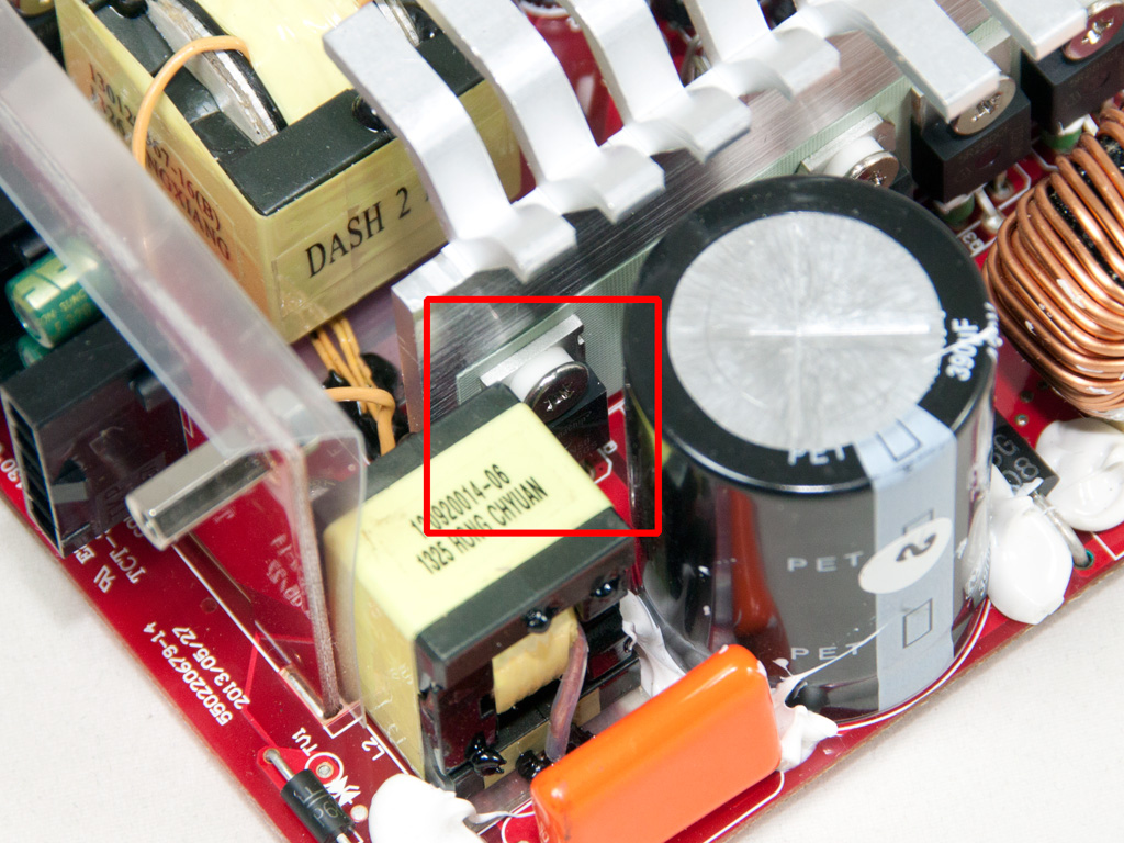
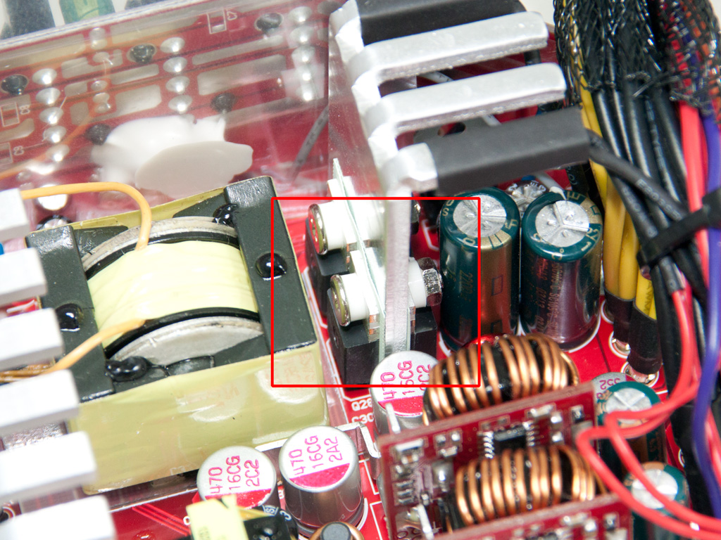
In the APFC, two Infineon IPP50R280CE fets and an STTH8R06D boost diode shape the current waveform to match the voltage one. The hold-up cap is provided my Matsushita (420 V, 390 μF, 105°C, HC series) and looks large enough for the needs of this unit.
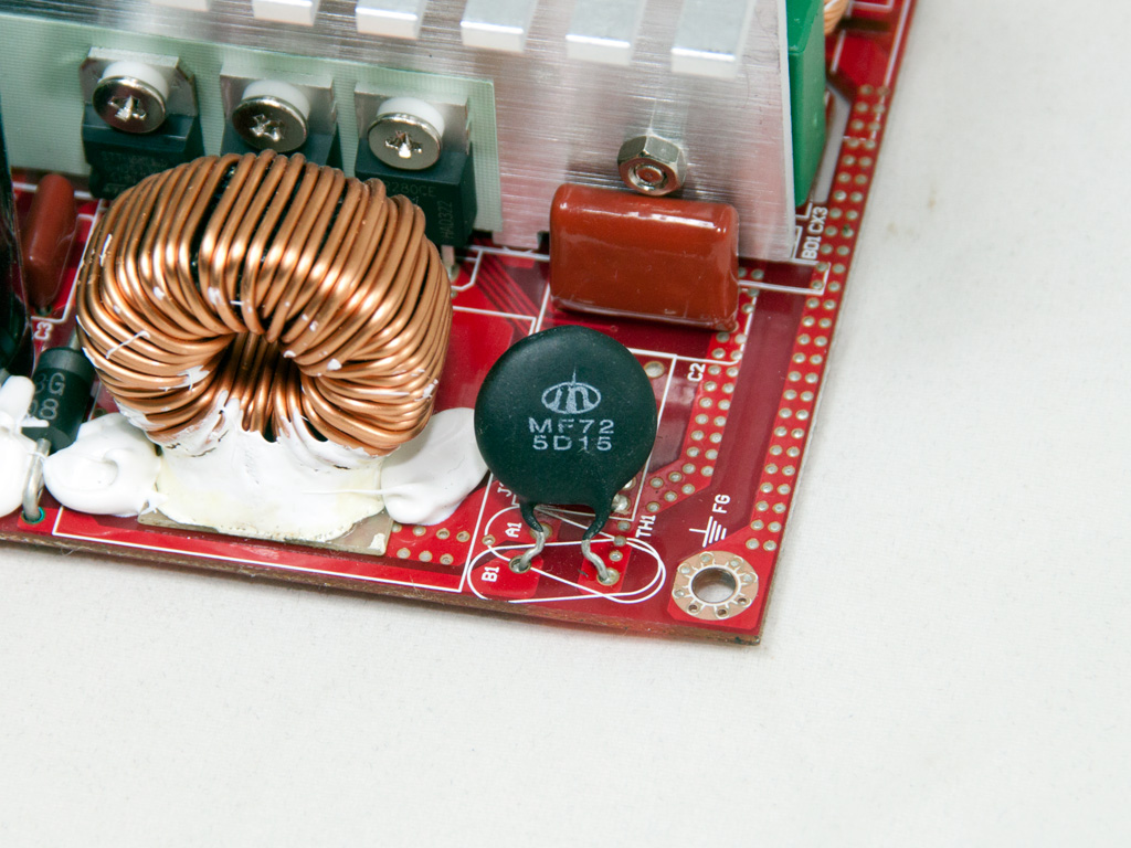
The NTC thermistor for protection against large inrush currents is quite big.
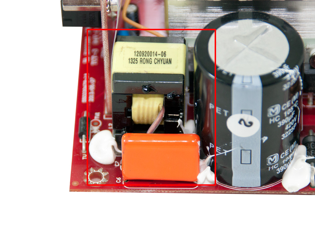
Next to the bulk cap are the capacitor and all inductive parts of the LLC resonant converter.
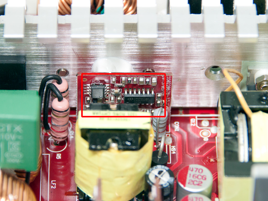
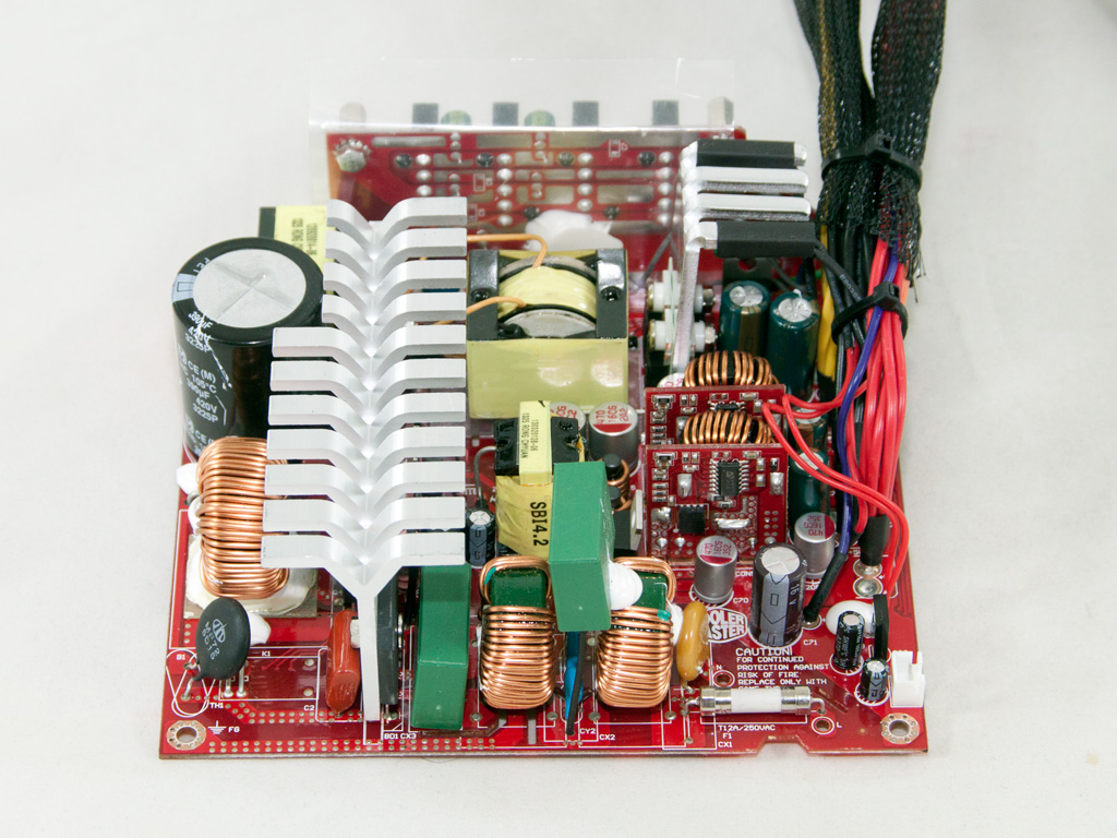
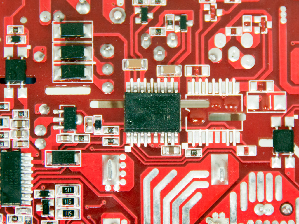
The PFC controller is sitting on this small vertical board. It is a CM6500TNX. This controller's included inrush-current-control function measures the inrush current during the start-up phase to protect the PSU and system if it is too high. The small IC next to it is a CM03X Green PFC controller that supports the main PFC controller and helps in achieving better efficiency.

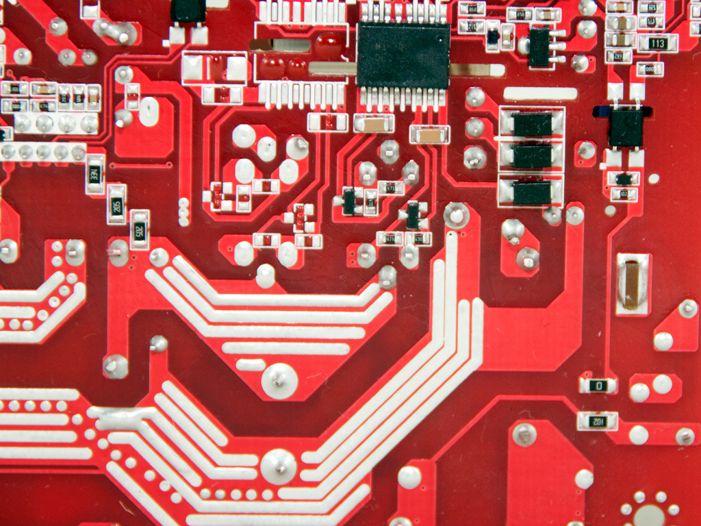
A pair of Magnachip MDP18N50 fets are used as main switchers.
The main transformer is really small!

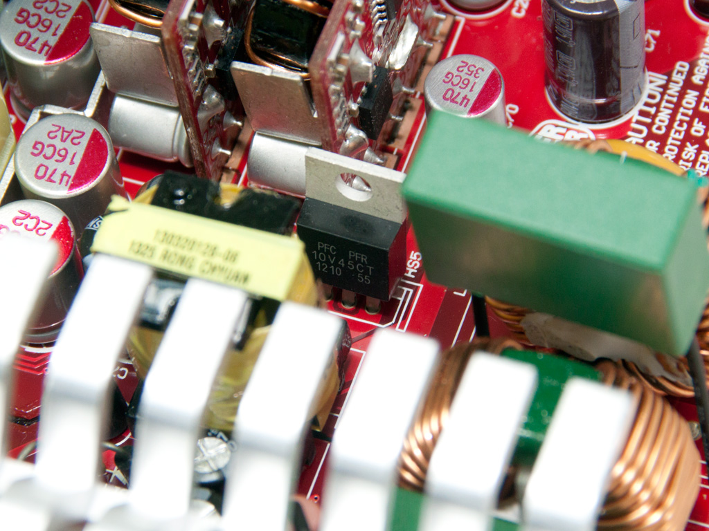
The standby PWM controller is an STR-A6069H IC, and the 5VSB rail is rectified by a PFR10V45CT SBR.


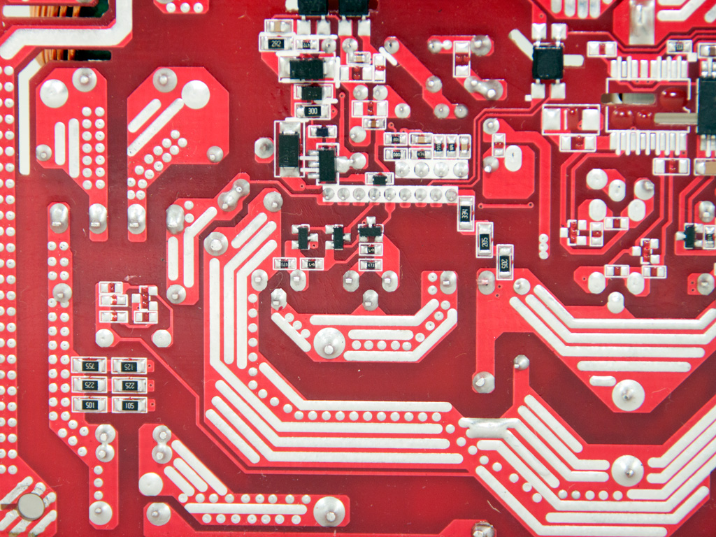
In the secondary side, a small heatsink with large fins holds four Infineon IPP041N04N fets which regulate the +12V rails. The secondary rails are generated by two small DC-DC converters. Each converter uses an APW7073 PWM controller along with a single fet.


Many polymer and Teapo electrolytic caps are used for filtering purposes.
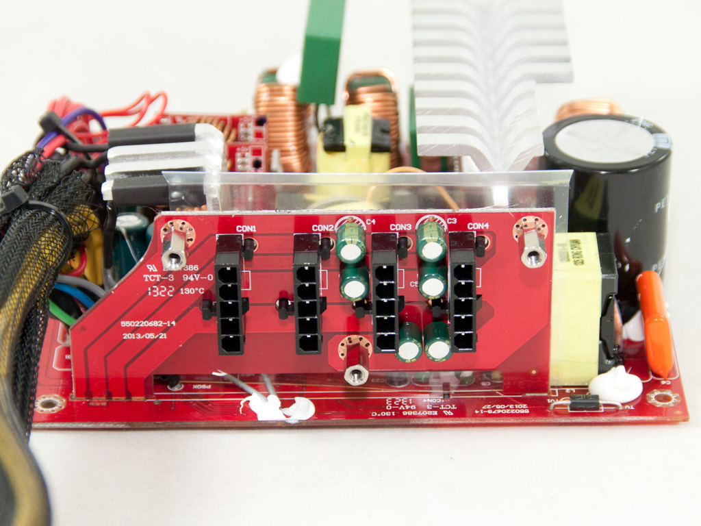

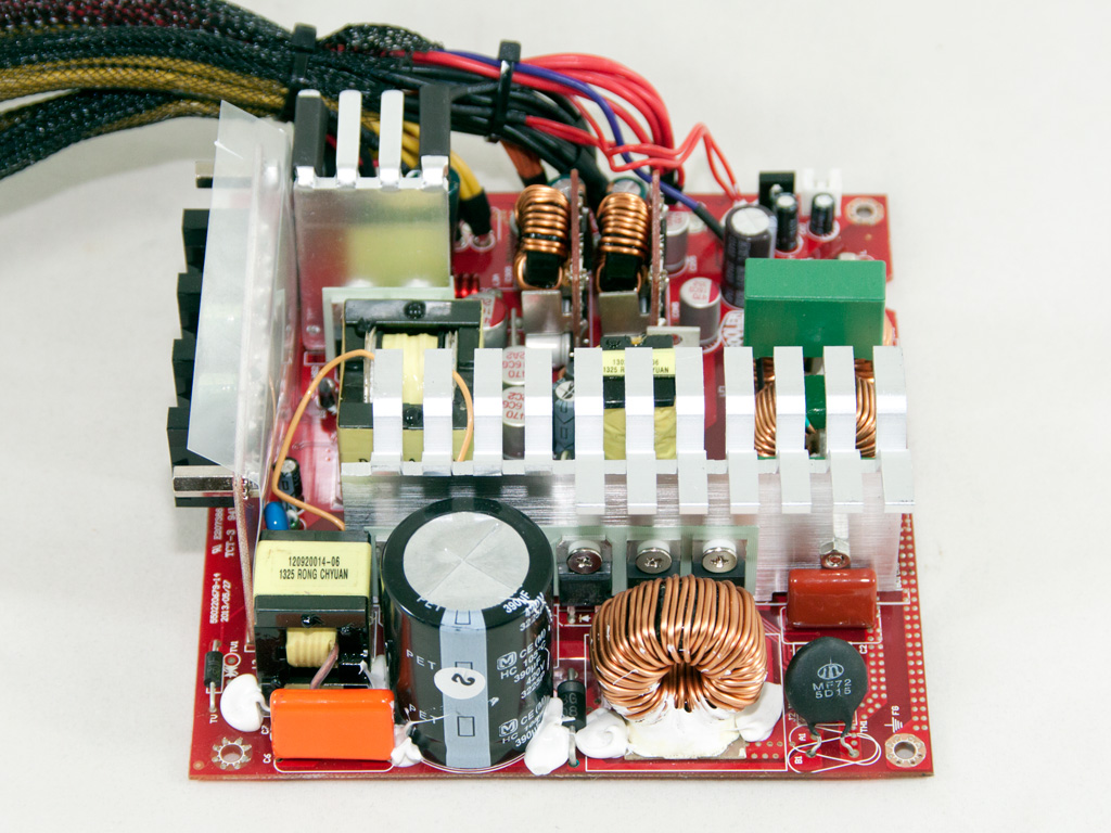
The 3D PCB design CM speaks of simply consists of the modular PCB being soldered directly onto the main one, without the use of bus bars or similar bridges. We can easily state that the description is then more of a marketing term, not an engineering one, but we really don't care what they call it as long as it minimizes energy losses. At the front of the modular PCB are several Suncon electrolytic caps. The caps are not the best choice as far as quality is concerned, but demands on this stage are rather low.


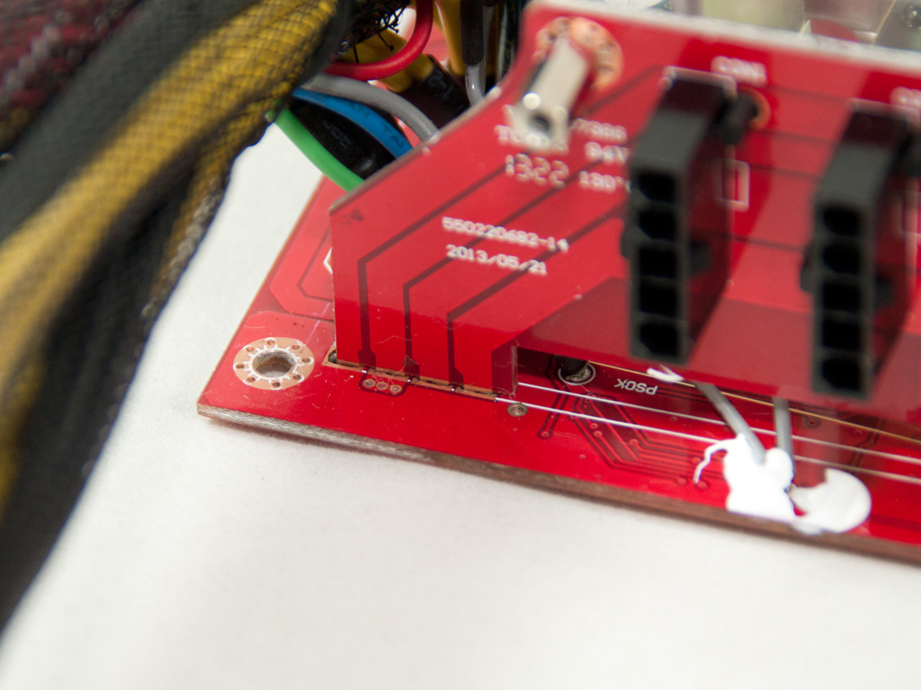
We found a small flaw on a trace line of the PCB's solder side, but the fresh production line is to blame for it. Normal samples won't have similar problems—their quality will be up to the standards we usually see from Enhance products.

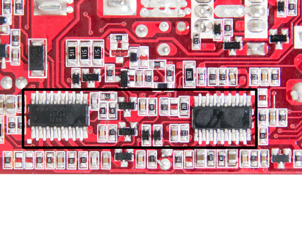
The rear of the main PCB hosts several interesting ICs: a CM02X under the transient filtering stage, which assists in minimizing energy loses on bleeding resistors, the LLC resonant controller—a Champion CM6901—, a SITI PS223 protections IC, and a Silicon Labs Si8233BD isolator interface.
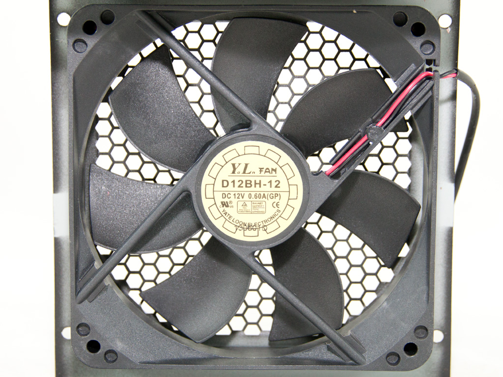

The fan is provided by Yate Loon and uses double ball-bearings to increase its lifetime. This fan is really strong, and we definitely didn't expect to see one in a Gold-certified PSU of medium capacity, but it is restricted to very low speeds most of the time since energy dissipation is also very low. The fan's model number is D12BH-12 (12 V, 2300 RPM, 89 CFM, 41 dBA).
Apr 27th, 2024 11:37 EDT
change timezone
Latest GPU Drivers
New Forum Posts
- Should I install Windows 10 or 11 for my new device (29)
- looking to build a new system and im considering asrock brand but i have some doubts/concerns. (18)
- Alphacool CORE 1 CPU block - bulging with danger of splitting? (38)
- Lenovo Thinkpad issue- text overlapping (0)
- Looking for recommendations to upgrade the GPU (10)
- TPU's Nostalgic Hardware Club (18478)
- Flashed wrong Bios (1)
- Best SSD for system drive (105)
- Asus Crosshair X670E - CPU Package temps (12)
- Help me identify rx 580 card ? (3)
Popular Reviews
- Ugreen NASync DXP4800 Plus Review
- HYTE THICC Q60 240 mm AIO Review
- Upcoming Hardware Launches 2023 (Updated Feb 2024)
- MOONDROP x Crinacle DUSK In-Ear Monitors Review - The Last 5%
- Thermalright Phantom Spirit 120 EVO Review
- FiiO K19 Desktop DAC/Headphone Amplifier Review
- Alienware Pro Wireless Gaming Keyboard Review
- AMD Ryzen 7 7800X3D Review - The Best Gaming CPU
- ASUS Radeon RX 7900 GRE TUF OC Review
- Gigabyte GeForce RTX 4070 Ti Super Gaming OC Review
Controversial News Posts
- Windows 11 Now Officially Adware as Microsoft Embeds Ads in the Start Menu (139)
- Sony PlayStation 5 Pro Specifications Confirmed, Console Arrives Before Holidays (117)
- NVIDIA Points Intel Raptor Lake CPU Users to Get Help from Intel Amid System Instability Issues (106)
- AMD "Strix Halo" Zen 5 Mobile Processor Pictured: Chiplet-based, Uses 256-bit LPDDR5X (103)
- US Government Wants Nuclear Plants to Offload AI Data Center Expansion (98)
- AMD's RDNA 4 GPUs Could Stick with 18 Gbps GDDR6 Memory (95)
- Developers of Outpost Infinity Siege Recommend Underclocking i9-13900K and i9-14900K for Stability on Machines with RTX 4090 (85)
- Windows 10 Security Updates to Cost $61 After 2025, $427 by 2028 (84)