 21
21
Corsair AX850 850 W Review
Voltage Regulation & Efficiency »A Look Inside
Before reading this page we strongly suggest to take a look at this article, which will help you understand the internal components of a PSU much better.
The OEM of AX850 is Seasonic. On the main PCB we find several pretty small heatsinks. You see these Gold PSUs have very low energy losses, thus operational temperatures are kept low and there is no need for large heatsinks.

The AC receptacle incorporates a Yun Pen EMI line filter which includes all necessary components (one X, two Y capacitors and two coils). On the main PCB there are one X and two Y capacitors, two coils and an MOV. There is also a thermistor along with an electromagnetic relay which bypasses it once the PSU starts to minimize energy losses and to allow it also to cool down. Near the relay and the thermistor resides an ICE2QR4765 Quasi-Resonant PWM Controller, which handles the standby mode of the PSU.

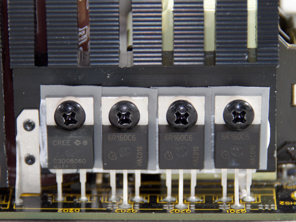

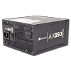
The bridge rectifiers, two GBU1506, are cooled passively by a heatsink. In APFC three mosfets (60R160C6) separate the intermediate DC voltage coming from the bridge rectifiers into constant pulse sequences. As boost diode a C3D08060A is used. The two parallel smoothing/reservoir capacitors are provided by Nippon Chemi-Con (420V, 390μF, 105°C, KMR). The main switches are two 60R160C6 mosfets. The PSU utilizes an LLC-resonant converter to achieve higher efficiency, and the resonant controller is a CM6901 which is housed on a vertical daughter-board right next to the resonant inductor. This controller operates the main switches in PWM mode at light loads and in FM mode at higher loads. Seasonic chose not to use an integrated transformer so two transformers are used in the resonant converter along with the main transformer.

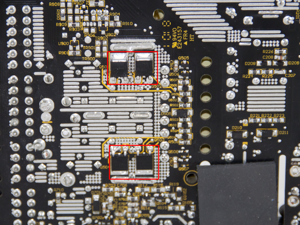
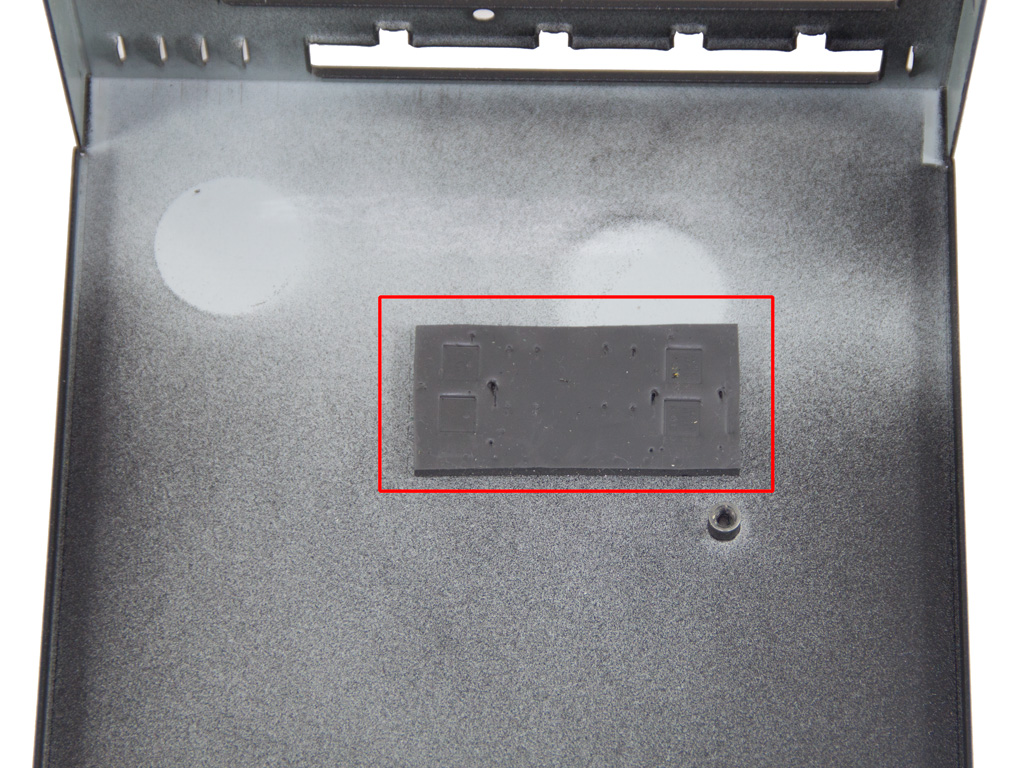


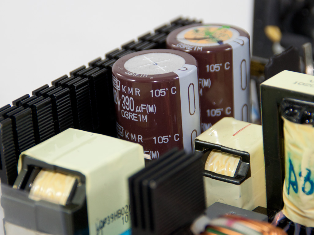
In the secondary we find several smaller heatsinks that cool the mosfets (four IPD031N06L) used for the +12V generation. These mosfets reside on the solder side of the main PCB and are also cooled from the casing through a thermal pad. The minor rails are generated from +12V with the use of two DC-DC converters. The latter are housed on the modular PCB, in order to minimize the distance that current has to travel and thus effectively decrease energy losses. Both converters use an APW7159 PWM controller and four PD060N03L mosfets. In the secondary side and on the modular PCB we meet many polymer capacitors, something that guarantees top performance along with increased life time. One of the few electrolytic capacitors we found is used in 5VSB regulation and it's provided from Nippon Chemi-Con too.

The protections of the PSU handles a PS223, which is added by an LM393 Dual Voltage Comparator.

Soldering quality and workmanship in general is very high.

The cooling fan is a San Ace 120 by SANYO DENKI (model number: 9S1212F404).
Apr 26th, 2024 03:10 EDT
change timezone
Latest GPU Drivers
New Forum Posts
- Best SSD for system drive (82)
- What phone you use as your daily driver? And, a discussion of them. (1484)
- What's your latest tech purchase? (20342)
- AMD RX 7000 series GPU Owners' Club (1087)
- im new to throttelstop and i think i messed it up by copying others any hints would be very much aprreciated (3)
- Horizontal black lines popping up on my screen? (4)
- Which new games will you be buying? (316)
- Alphacool CORE 1 CPU block - bulging with danger of splitting? (20)
- Black screen after muting (5)
- What are you playing? (20530)
Popular Reviews
- Fractal Design Terra Review
- Thermalright Phantom Spirit 120 EVO Review
- Corsair 2000D Airflow Review
- ASUS GeForce RTX 4090 STRIX OC Review
- NVIDIA GeForce RTX 4090 Founders Edition Review - Impressive Performance
- ASUS GeForce RTX 4090 Matrix Platinum Review - The RTX 4090 Ti
- MSI GeForce RTX 4090 Suprim X Review
- Gigabyte GeForce RTX 4090 Gaming OC Review
- MSI GeForce RTX 4090 Gaming X Trio Review
- MSI GeForce RTX 4090 Suprim Liquid X Review
Controversial News Posts
- Sony PlayStation 5 Pro Specifications Confirmed, Console Arrives Before Holidays (117)
- Windows 11 Now Officially Adware as Microsoft Embeds Ads in the Start Menu (113)
- NVIDIA Points Intel Raptor Lake CPU Users to Get Help from Intel Amid System Instability Issues (106)
- AMD "Strix Halo" Zen 5 Mobile Processor Pictured: Chiplet-based, Uses 256-bit LPDDR5X (101)
- US Government Wants Nuclear Plants to Offload AI Data Center Expansion (98)
- AMD's RDNA 4 GPUs Could Stick with 18 Gbps GDDR6 Memory (88)
- Developers of Outpost Infinity Siege Recommend Underclocking i9-13900K and i9-14900K for Stability on Machines with RTX 4090 (85)
- Windows 10 Security Updates to Cost $61 After 2025, $427 by 2028 (84)