 3
3
Corsair RM Series 650 W Review
Voltage Regulation, Hold-up Time & Inrush Current »A Look Inside & Component Analysis
Before reading this page, we strongly suggest a look at this article, which will help you understand the internal components of a PSU much better. Our main tool for the disassembly of the PSU is a Thermaltronics TMT-9000S soldering and rework station. It is of extreme quality and is equipped with a matching de-soldering gun. With such equipment in hand, breaking apart every PSU is like a walk in the park!Contrary to the other RM units we have tested so far (RM750 and RM850), this one is made by Channel Well Technology, or CWT, a highly respected OEM with lots of experience and many worthwhile products. Corsair has cooperated with CWT many times in the past, releasing incredibly well-performing and reliable PSU products, so we expect the RM650 to carry on in the same way.


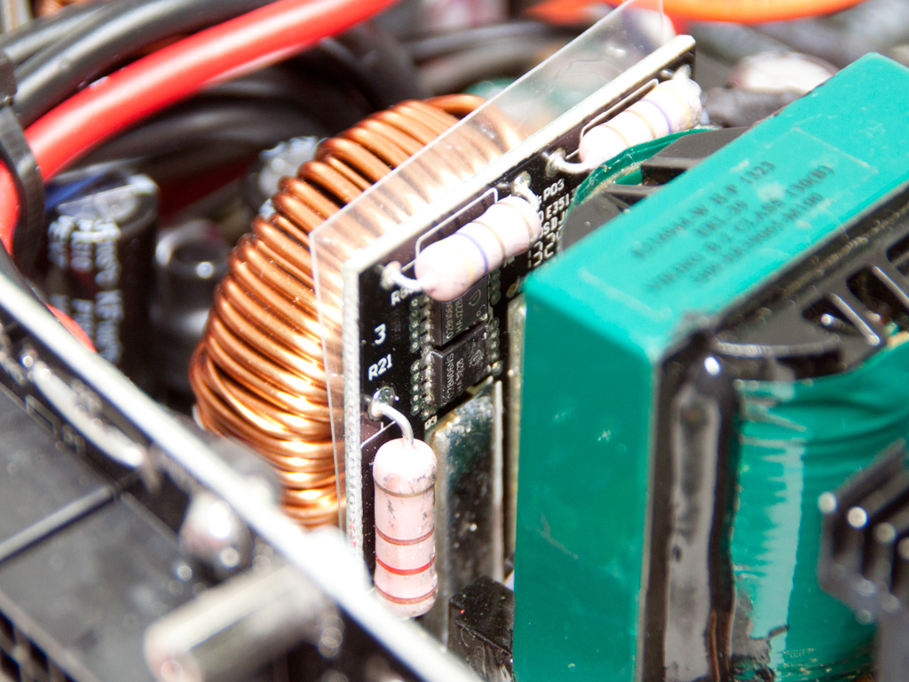
The platform isn't cutting edge, but it is based on an older design to lower production cost. Corsair didn't use an LLC resonant converter to boost efficiency, but instead exploited a plain topology which is controlled by an older IC, the Champion CM6802 usually found in affordable Gold PSUs. VRMs in the secondary side handle the minor rails, and there is no proper heatsink for the +12V fets, which seems to be a trend in even semi-passive units nowadays. Apparently fets with very low Rds(on) values are used, which allows for such a design by keeping heat/energy dissipation low.
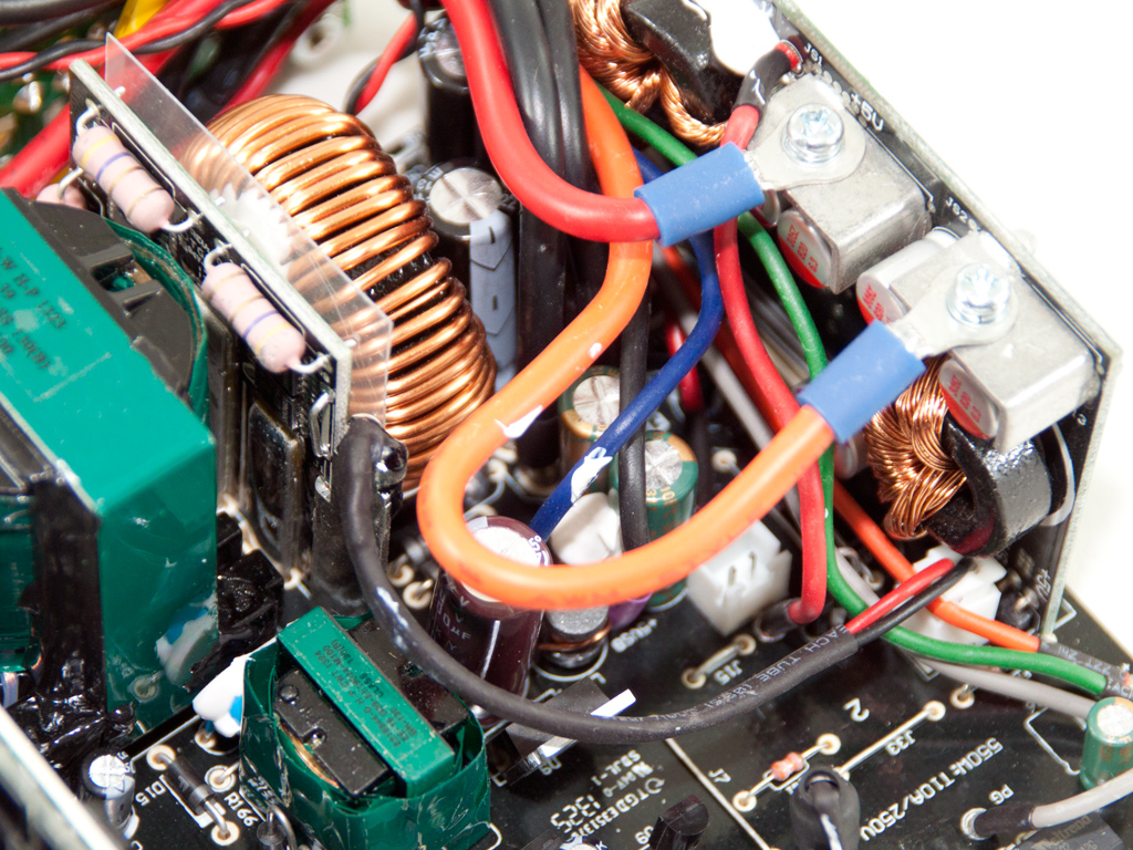
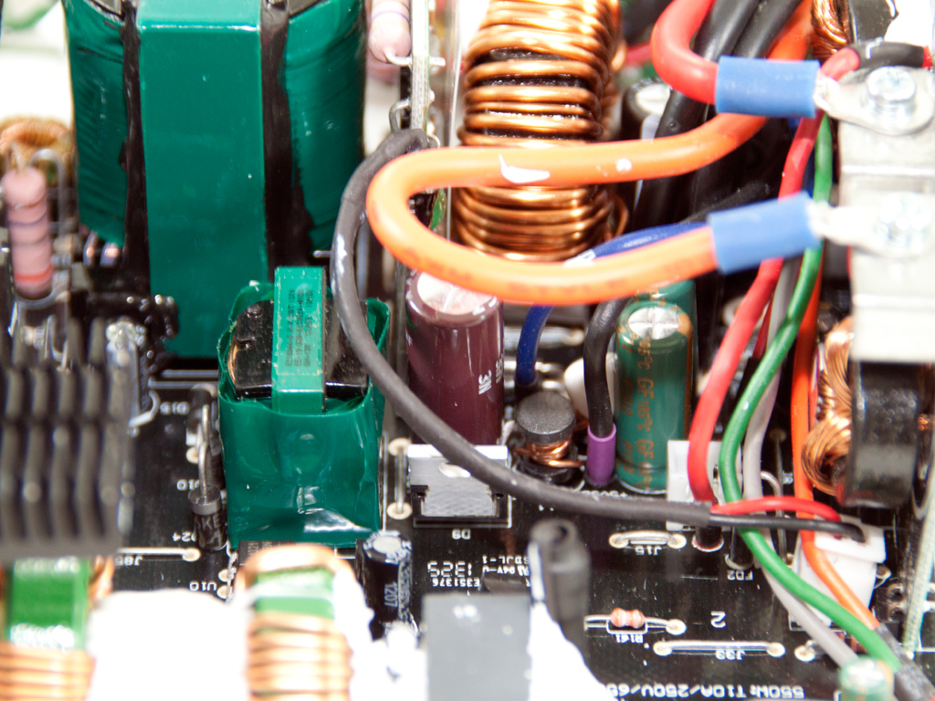
The transient filter starts with a pair of Y caps at the AC receptacle and continues on the main PCB with two X caps, a pair of Y caps after the bridge rectifier, two CM chokes, and an MOV completely covered in white glue; we had to excavate it.

The bridge rectifier is bolted to the primary heatsink. Its marking were on the other side and we weren't in the mood to desolder it.


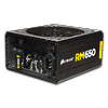
An SCS110AG boost diode and two FMP20N60S1 fets are used in the APFC converter. The hold-up cap is provided by Panasonic (400 V, 470 µF, 105C), and next to it resides the NTC thermistor which protects the unit against large inrush currents. There is also a relay that isolates the aforementioned thermistor once it finishes its job.


Two Vishay SiHF22N60E fets are the main switchers.

The combo PFC/PWM controller is a Champion CM6802 IC. It is installed on a vertical daughter-board.
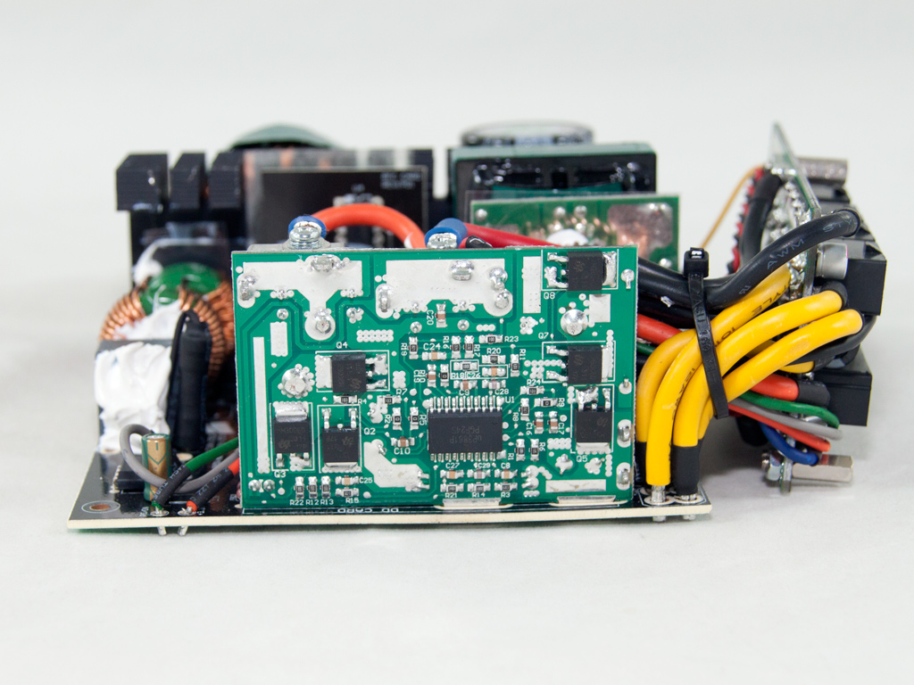


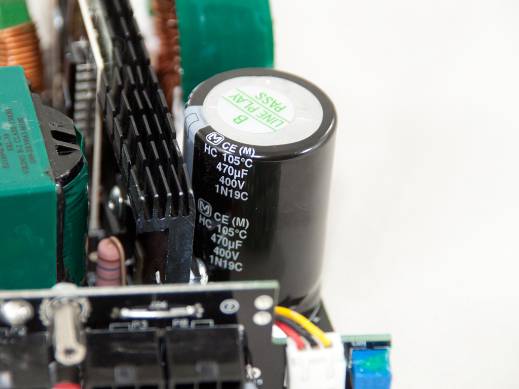
There is no heatsink in the secondary side, and the fets that generate the +12V rail, four Infineon BSC028N06NSs, are installed on a vertical daughter-board that almost touches the main transformer. They installed these fets so close to the transformer to restrict energy losses, especially at higher loads. Four busbars are attached to the same board; not only do these provide cooling, they also provide earth and transfer power. A thermistor is attached to one of the above busbars to provide temperature information to the fan control circuit.
The filtering caps in the secondary side are provided by Teapo and CapXon, definitely not the best choices for a PSU of this price range, but we have seen worse. The 5VSB circuit thankfully uses a Chemi-Con cap.


The VRMs that generate the minor rails are hosted on this PCB. Each VRM uses three M3006D fets and the common uP3861P IC PWM controller. Two Enesol polymer caps and four Aishi ones on the same board handle ripple filtering.


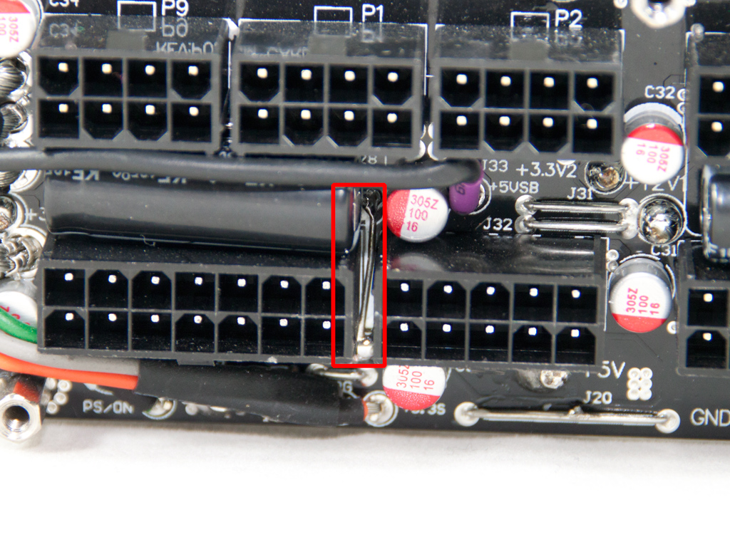

Six small polymer caps at the front of the modular PCB provide some extra ripple filtering. We also noticed that our sample suffers from the same problem as the OklahomaWolf reviewed at Jonnyguru. To be more specific, some of the 5V pins on the 24-pin ATX connector don't provide any voltage because CWT forgot to install a grounding bridge. This may not be a huge problem since modern systems only utilize the 5V rail lightly as its remaining wires will easily cope with the task, but it is still a flaw for which we will deduct some points off our final rating. We soldered a ground bridge to the PSU's vacant spot before reassembly to fix the problem.

Soldering on the rear of the modular PCB wasn't up up to the standards of other CWT/Corsair products.

The supervisor IC is soldered to the main PCB; it is a Weltrend WT7502. This IC doesn't support OCP and OTP, though Corsair states this unit to feature the above protections. OCP most likely isn't present since it doesn't have any usage in a 650 W, single +12V rail PSU, but OTP may be present since the PSU shut down once temperatures during our overload test surpassed 46°C.


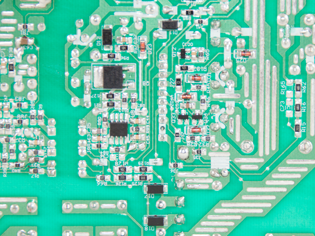
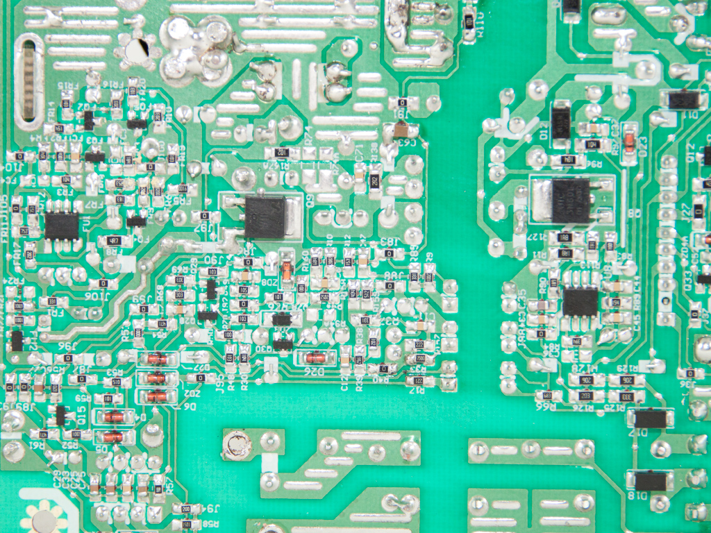
Soldering quality on the main PCB is decent, but we noticed some sloppy soldering joints; CWT didn't do their best with this unit.

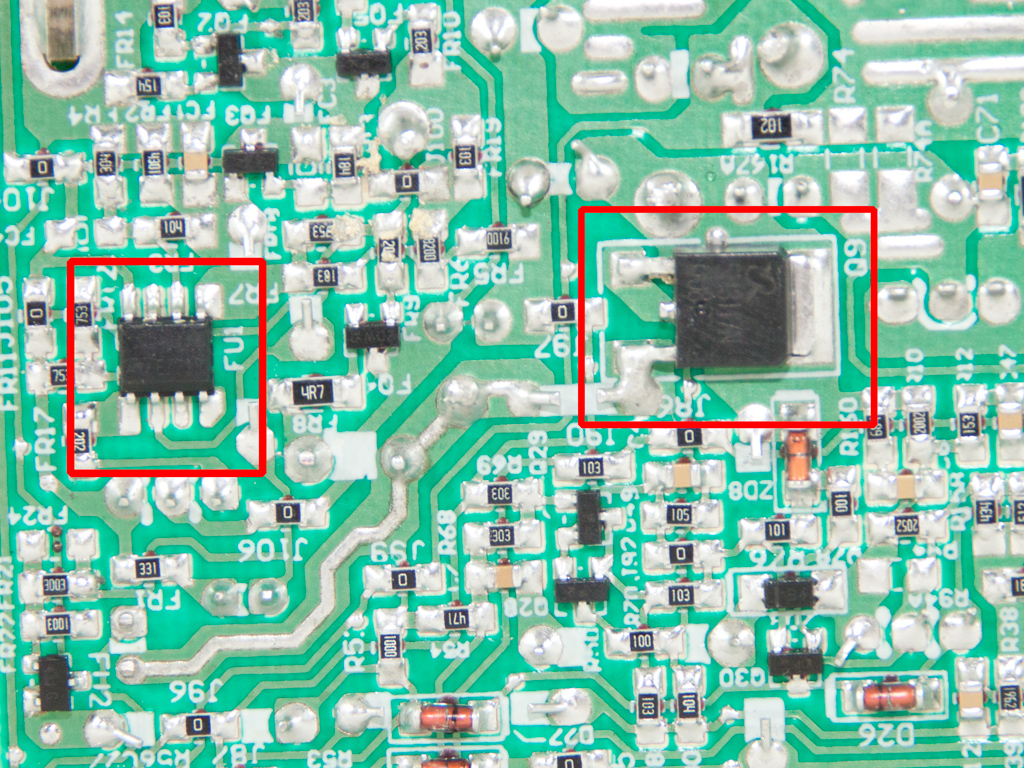

We found two mosfets, a UTC 3N60L and SM3117NSU, on the main side of the primary PCB. The latter is probably used by the 5VSB circuit; along with an SBL1040CTP SBR.


The fan is the same as the one in the RM750/850 units. It operation is silent at even full speed, and it uses rifle bearings, an enhanced type of the plain sleeve bearings. As you can see from the photos above, its model number is NR135L (12 V, 0.22 A). Finally, the fan profile is thankfully less relaxed than that of the RM750/850 units, which then puts less stress on heat-sensitive components like electorlytic caps.
Apr 25th, 2024 01:26 EDT
change timezone
Latest GPU Drivers
New Forum Posts
- (Anti) SFF fun house (349)
- Github comments used to push malware via Microsoft repo urls (1)
- What's your latest tech purchase? (20337)
- The Official Linux/Unix Desktop Screenshots Megathread (694)
- XFX RX470 8GB no video and error 43 (27)
- Cinebench crashed my PC. My Wi-Fi stopped working, and I keep getting a "Please wait" screen when I boot up my PC. (31)
- im new to throttelstop and i think i messed it up by copying others any hints would be very much aprreciated (1)
- Aida64 cache mem OC (7)
- I am getting artifacting when I change Windows security settings. Is my GPU failing, or is this just a Windows issue? (10)
- Is there a technical reason that Windows 11 doesn't have built into it battery charge limitation? (42)
Popular Reviews
- Fractal Design Terra Review
- Thermalright Phantom Spirit 120 EVO Review
- Corsair 2000D Airflow Review
- Minisforum EliteMini UM780 XTX (AMD Ryzen 7 7840HS) Review
- ASUS GeForce RTX 4090 STRIX OC Review
- NVIDIA GeForce RTX 4090 Founders Edition Review - Impressive Performance
- ASUS GeForce RTX 4090 Matrix Platinum Review - The RTX 4090 Ti
- MSI GeForce RTX 4090 Suprim X Review
- MSI GeForce RTX 4090 Gaming X Trio Review
- Gigabyte GeForce RTX 4090 Gaming OC Review
Controversial News Posts
- Sony PlayStation 5 Pro Specifications Confirmed, Console Arrives Before Holidays (116)
- NVIDIA Points Intel Raptor Lake CPU Users to Get Help from Intel Amid System Instability Issues (106)
- AMD "Strix Halo" Zen 5 Mobile Processor Pictured: Chiplet-based, Uses 256-bit LPDDR5X (101)
- US Government Wants Nuclear Plants to Offload AI Data Center Expansion (98)
- Windows 10 Security Updates to Cost $61 After 2025, $427 by 2028 (84)
- Developers of Outpost Infinity Siege Recommend Underclocking i9-13900K and i9-14900K for Stability on Machines with RTX 4090 (84)
- TechPowerUp Hiring: Reviewers Wanted for Motherboards, Laptops, Gaming Handhelds and Prebuilt Desktops (78)
- AMD's RDNA 4 GPUs Could Stick with 18 Gbps GDDR6 Memory (74)