 8
8
Enermax Triathlor FC 550 W Review
Voltage Regulation, Hold-up Time & Inrush Current »A Look Inside & Component Analysis
Before reading this page, we strongly suggest a look at this article, which will help you understand the internal components of a PSU much better. Our main tool for the disassembly of the PSU is a Thermaltronics TMT-9000S soldering and rework station. It is of extremely quality and is equipped with a matching de-soldering gun. With such equipment in hand, breaking apart every PSU is like a walk in the park!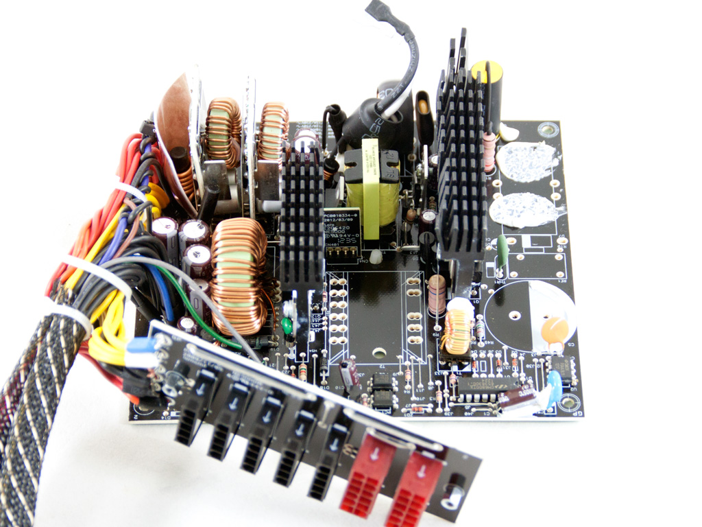


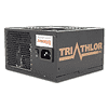
This time, Enermax didn't go to another vendor for their budget-oriented units, but has, instead, built the unit themselves. This is good news of course, since they have been manufacturing PSUs for quite a long time, releasing many excellent products to date. However, their main problem was and most likely still is their high production cost, which has kept them from making a strong entry into the mainstream and mid-end categories, but this will hopefully change with the Triathlor series. The platform of this PSU uses a classic design, since we don't come across an exotic topology in the primary side, which would prove unnecessary for a Bronze unit, and the secondary side uses synchronous rectification for +12V and two DC-DC converters for the minor rails. We had to remove some components to provide you with a clearer view—namely, the APFC cap and choke, and the main transformer.
The first part of the transient filtering stage is housed on a small PCB right behind the AC receptacle. There, we found four Y caps, a single X cap, a CM choke, and a CM02X IC that discharges the X cap when AC voltage is disconnected. The second part of the transient filter is located on the main PCB and only includes a CM choke and an MOV.
The single bridge rectifier is bolted onto a dedicated heatsink. We already removed many parts from the PSU and didn't feel like removing this one just to identify it.


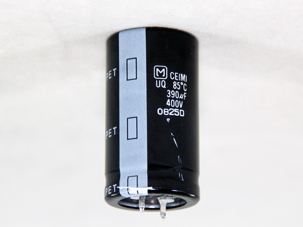
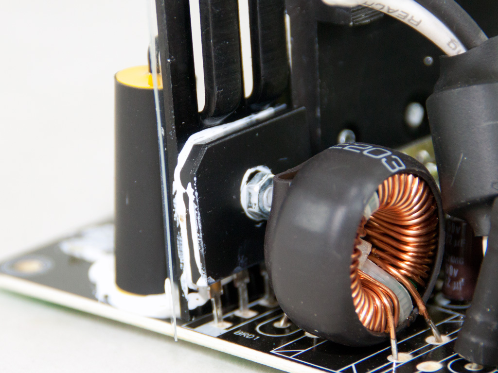
The APFC section has two K18A60 fets and a 15ETH06 boost diode. The single hold-up cap is provided by Matsushita/Panasonic (400 V, 390 μF, 85°C). Finally, two CEP14N5 are employed as main switchers.
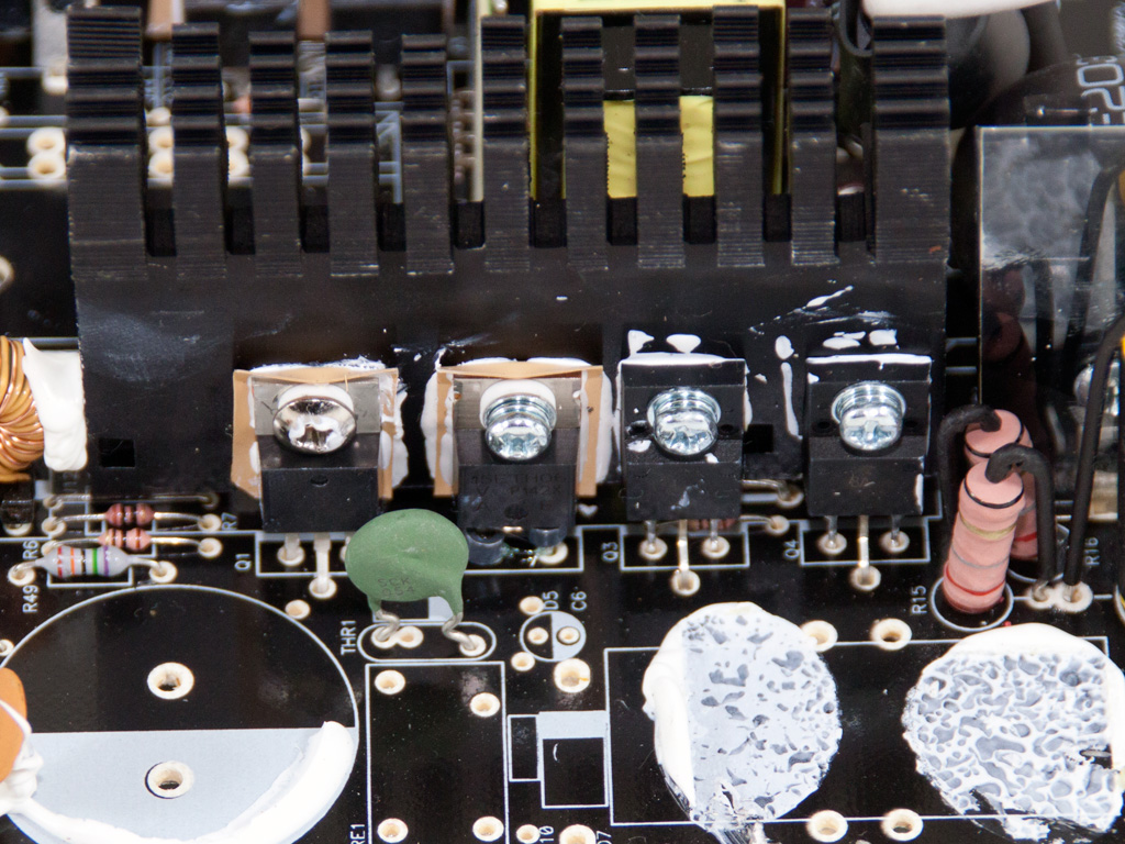
The main transformer of the PSU is small because it has to handle very little power.

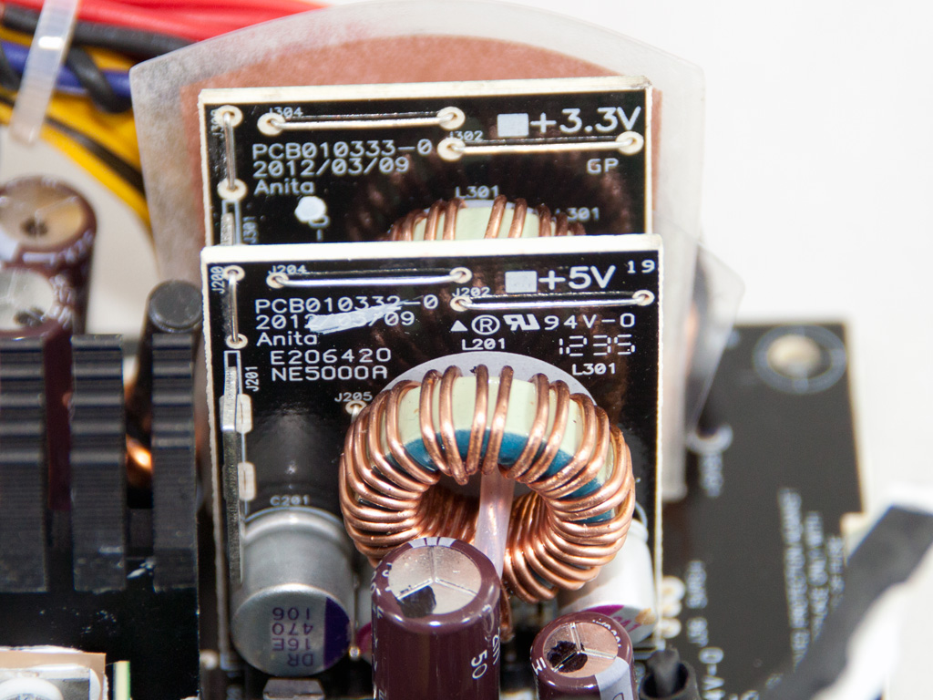

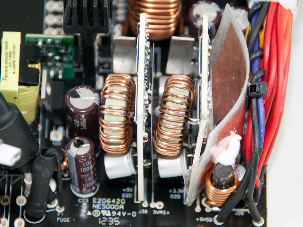

Four CEP6056 fets on the secondary side rectify the +12V rail. The minor rails are generated by two small DC-DC converters, and three fets and a PWM controller are installed with each one.


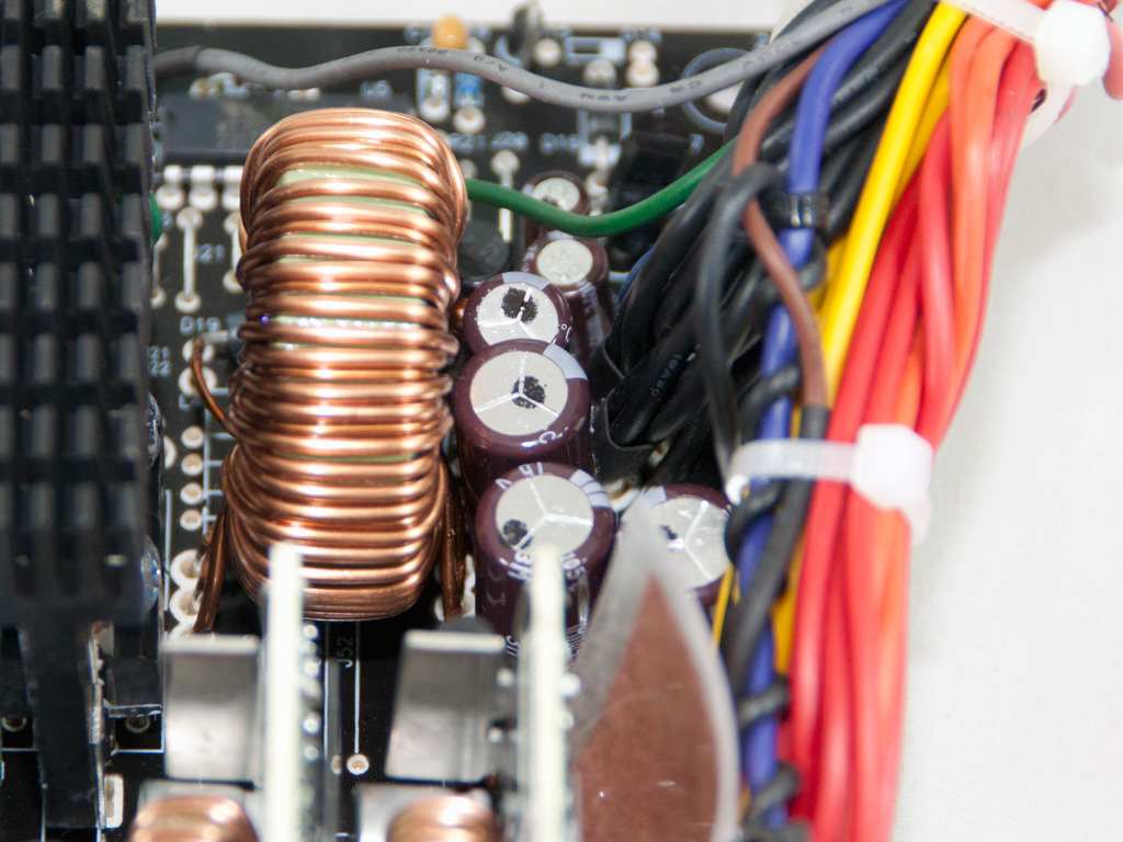
All filtering caps of the secondary side are provided by Nippon Chemi-Con and are rated at 105°C.
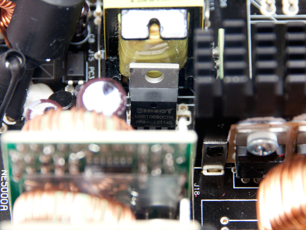
The 5VSB rail rectifies an MBR10B60CTH diode.

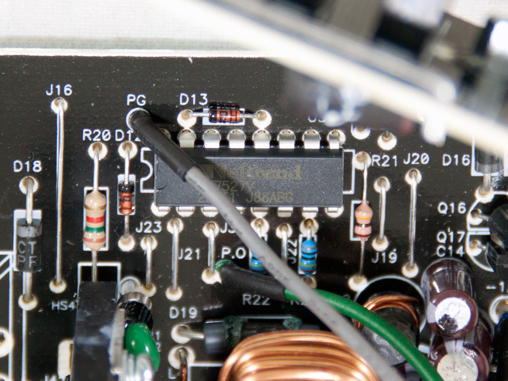
The combo PFC/PWM controller is a Champion CM6800 IC and the protections of the unit are handled by a Weltrend WT7527V IC. It supports OCP for up to two +12V rails, which matches the specifications of the unit. Both of the aforementioned ICs are installed on the component side of the main PCB.
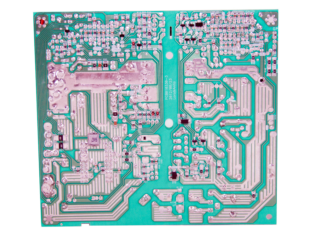
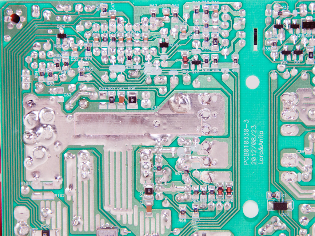
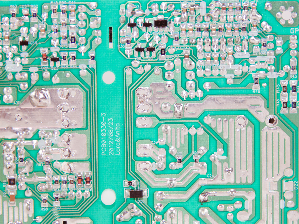

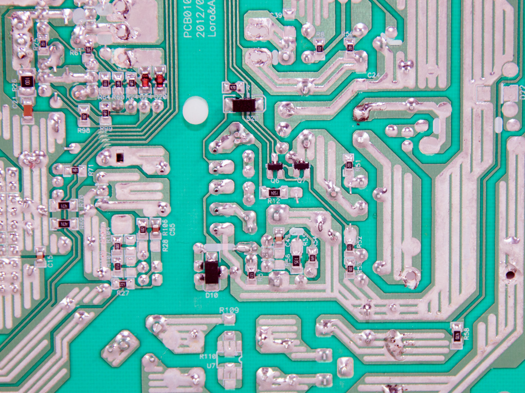
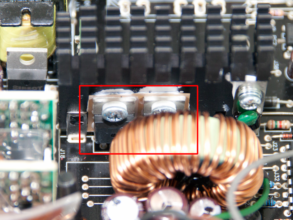
Soldering quality is good, although definitely not amongst the best we have ever seen. We spotted two current sense resistors under the +12V islands, so this unit really does have two +12V rails.
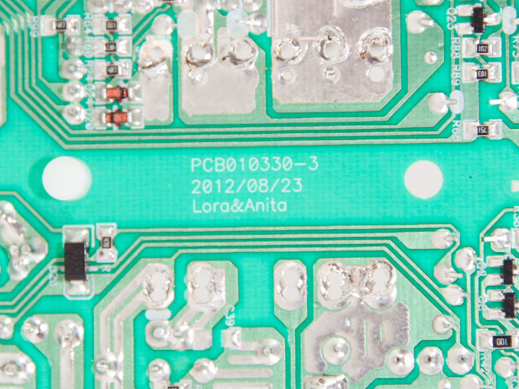
Not only Lora but also Anita signs the unit's PCB.
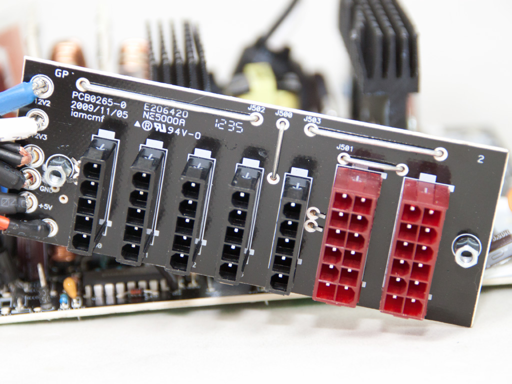
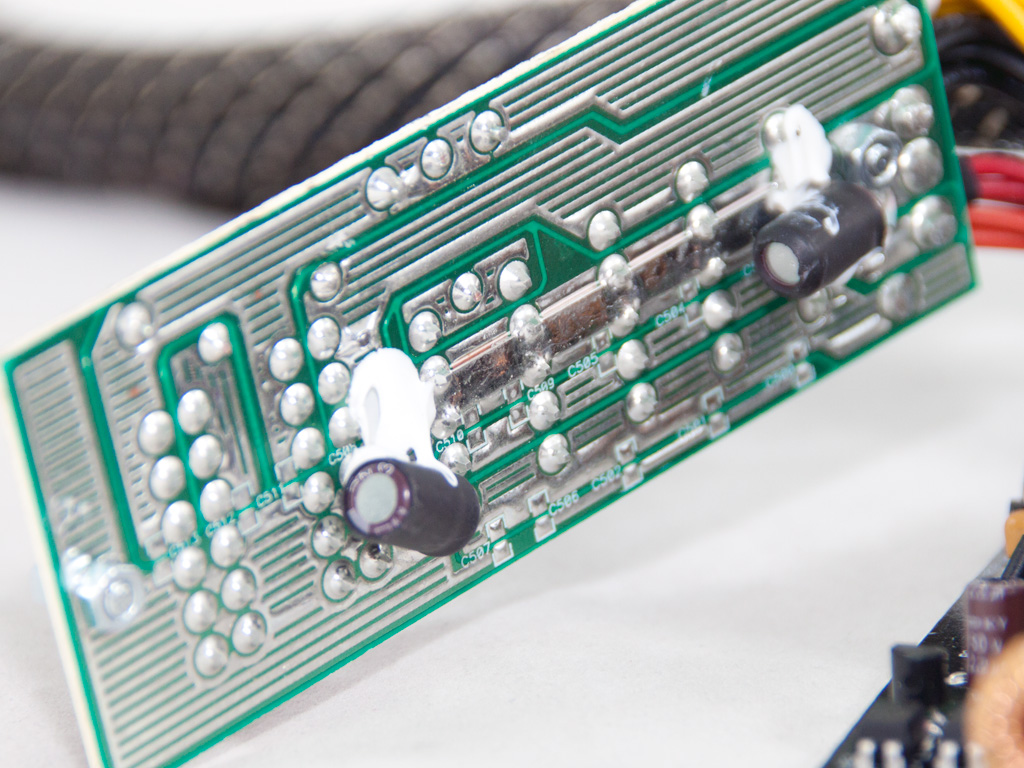
The small modular PCB includes seven sockets. On its rear side, two small electrolytic caps provide some extra filtering.
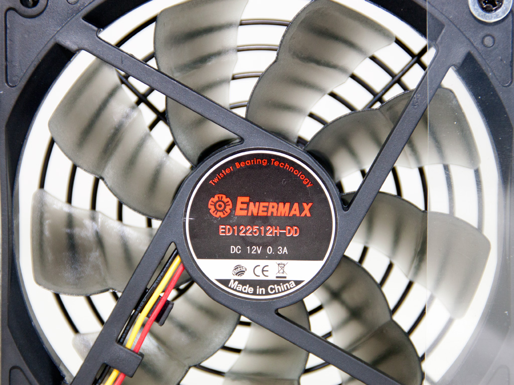
The nine-blade cooling fan carries the Enermax logo, and its model number is ED122512H-DD (12V, 0.3A). According to its maker, it uses twister bearings for lower noise output and increased lifespan, and its specially designed blades, named Batwings, offer up to 20% more airflow as compared to conventional blades.
May 12th, 2024 04:58 EDT
change timezone
Latest GPU Drivers
New Forum Posts
- FINAL FANTASY XIV: Dawntrail Official Benchmark (85)
- Ryzen 7 5800X is it worthed upgrade from Ryzen 7 5700X ? (10)
- Purchased an AX1200i PSU as part of some forward planning, what tier is this PSU? (5)
- PSU Option for my PC (6)
- What's your latest tech purchase? (20516)
- monitor w good contrast and viewing angle for my sister with eye problems (14)
- Flash VBIOS to turn RX 580 2048SP into RX 570 (38)
- X670 owners, what kind of PCH temps do you you see? (20)
- What's an inexpensive AIO product line with a strong pump and low price? (102)
- Homeworld 3 [Official Thread] (13)
Popular Reviews
- ZMF Caldera Closed Planar Magnetic Headphones Review
- ThundeRobot ML903 NearLink Review
- Corsair MP700 Pro SE 4 TB Review
- Bykski CPU-XPR-C-I CPU Water Block Review - Amazing Value!
- CHERRY XTRFY M64 Pro Review
- Upcoming Hardware Launches 2023 (Updated Feb 2024)
- ASRock NUC BOX-155H (Intel Core Ultra 7 155H) Review
- AMD Ryzen 7 7800X3D Review - The Best Gaming CPU
- Corsair iCUE Link RX120 RGB 120 mm Fan Review
- ASUS Radeon RX 7900 GRE TUF OC Review
Controversial News Posts
- Intel Statement on Stability Issues: "Motherboard Makers to Blame" (266)
- AMD to Redesign Ray Tracing Hardware on RDNA 4 (206)
- Windows 11 Now Officially Adware as Microsoft Embeds Ads in the Start Menu (171)
- NVIDIA to Only Launch the Flagship GeForce RTX 5090 in 2024, Rest of the Series in 2025 (147)
- Sony PlayStation 5 Pro Specifications Confirmed, Console Arrives Before Holidays (119)
- AMD's RDNA 4 GPUs Could Stick with 18 Gbps GDDR6 Memory (114)
- NVIDIA Points Intel Raptor Lake CPU Users to Get Help from Intel Amid System Instability Issues (106)
- AMD Ryzen 9 7900X3D Now at a Mouth-watering $329 (104)