 0
0
In Win GreenMe 650 W Review
Voltage Regulation & Efficiency »A Look Inside
Before reading this page, we strongly suggest a look at this article, which will help you understand the internal components of a PSU better.


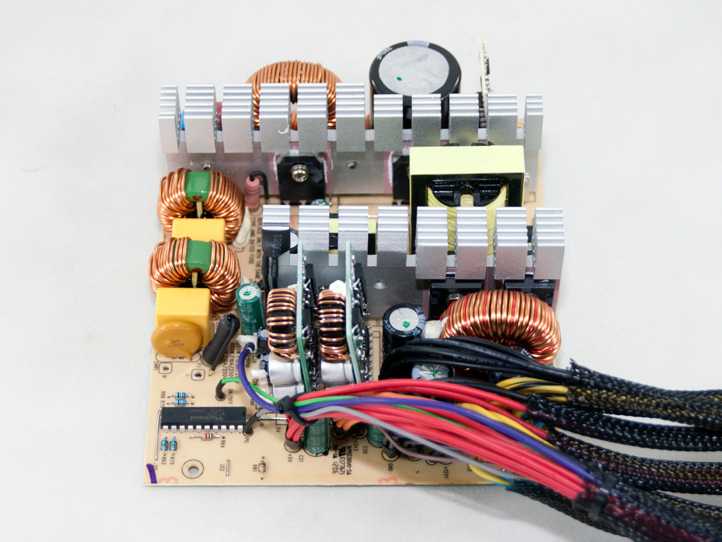
The maker of this PSU is In Win, which, as it seems, has the necessary know-how and the production facilities to manufactur their own PSU. The main, single-sided PCB is small and not densely populated. Also, the design is not modern, although DC-DC converters are used with the secondary side. The primary side utilizes a double-forward topology, while the secondary side uses a passive rectification scheme for the generation of +12V.
The transient filter starts at the AC receptacle with two Y caps. The main power cables are wrapped around a ferrite bead in an effort to suppress EMI. On the main PCB, we find the second stage of the transient filter consisting of two X, two Y caps located after the bridge rectifier, an MOV, and two CM chokes.

The two parallel bridge rectifiers are bolted on the primary heatsink and their model number is GBU606. Each one can handle up to 6 A of current and double that amount combined.


In the APFC, two Toshiba TK20J50D fets, along with a boost diode, help in shaping the sinusoidal input current to match the corresponding mains input voltage. The hold-up cap is provided by Panasonic (390μF, 420V, 105°C, HC series).


As main switchers, two TK15J50D fets are used. The combo PFC/PWM controller resides in a vertical daughter-board and is a Champion CM6802 IC, which is an upgraded version of the famous CM6800 found in numerous PSUs. The small transformer right in front of the vertical PCB that holds the CM6802 is used for driving the main switchers.


The secondary side uses passive components, so four MBR4060PT SBRs rectify the +12V rail. The minor rails are generated by two DC-DC converters with each one consisting of two pairs of M3016D and M3004D fets, and a uP3872B PWM controller, an IC we never encountered before.


All filtering caps on the secondary side are electrolytic with half of them being provided by Teapo and the rest by Samxon. We would highly prefer all to be made by Teapo.

The supervisor IC that handles all PSU protections is installed on the main PCB and its model number is a Weltrend WT7579 IC.

The standby PWM controller is a PI TNY278PN IC.

The 5VSB rail is rectified by an STPS2045CT SBR. The output is filtered by a Teapo cap and a really small inductor.


The soldering quality on the main PCB is fairly good, especially if we take into account the price category of the GreenME 650. We also found four current sense resistors under the +12 V islands, matching the advertised number of +12V virtual rails.

The cooling fan is provided by ADDA and its model number is AD1212LB-A70GL (12V, 0.24A, 1400 RPM, 56 CFM, 28dBA). It uses ball bearings and is, although it spins at relative low RPM, noisy at full speeds in our tests.
May 10th, 2024 07:52 EDT
change timezone
Latest GPU Drivers
New Forum Posts
- Noisy rx 6600 xt (2)
- Graphics card running at 8x 4.0 not 16x 4.0 (21)
- Any suggestion for hosting to test something ? (5)
- What's your latest tech purchase? (20492)
- ALPHACOOL - ideas for IMPROVING products and NEW products (5)
- AM5 boot times improve RADICALLY with memory context restore enabled (30)
- What are you playing? (20610)
- RM750x (2021) enough for my 5800X3D + 7900XT system? (14)
- Homeworld 3 [Official Thread] (0)
- EKWB - ideas for IMPROVING products and NEW products (0)
Popular Reviews
- CHERRY XTRFY M64 Pro Review
- Bykski CPU-XPR-C-I CPU Water Block Review - Amazing Value!
- Corsair iCUE Link RX120 RGB 120 mm Fan Review
- Corsair MP700 Pro SE 4 TB Review
- ThundeRobot ML903 NearLink Review
- Upcoming Hardware Launches 2023 (Updated Feb 2024)
- Finalmouse UltralightX Review
- AMD Ryzen 7 7800X3D Review - The Best Gaming CPU
- Sapphire Radeon RX 7700 XT Pure Review
- ASUS Radeon RX 7900 GRE TUF OC Review
Controversial News Posts
- Intel Statement on Stability Issues: "Motherboard Makers to Blame" (264)
- AMD to Redesign Ray Tracing Hardware on RDNA 4 (206)
- Windows 11 Now Officially Adware as Microsoft Embeds Ads in the Start Menu (169)
- NVIDIA to Only Launch the Flagship GeForce RTX 5090 in 2024, Rest of the Series in 2025 (144)
- Sony PlayStation 5 Pro Specifications Confirmed, Console Arrives Before Holidays (119)
- AMD's RDNA 4 GPUs Could Stick with 18 Gbps GDDR6 Memory (114)
- NVIDIA Points Intel Raptor Lake CPU Users to Get Help from Intel Amid System Instability Issues (106)
- AMD Ryzen 9 7900X3D Now at a Mouth-watering $329 (104)