 2
2
In Win GreenMe 750 W Review
Voltage Regulation, Hold-up Time & Inrush Current »A Look Inside & Component Analysis
Before reading this page, we strongly suggest a look at this article, which will help you understand the internal components of a PSU much better. Our main tool for the disassembly of the PSU is a Thermaltronics TMT-9000S soldering and rework station. It is of extreme quality and is equipped with a matching de-soldering gun. With such equipment in hand, breaking apart every PSU is like a walk in the park!
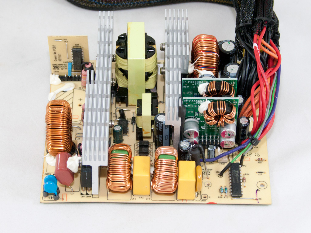
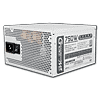
In Win makes the GreenMe units and most of the other PSUs they offer themselves since they have the necessary expertise and the production lines to build PSUs. Although the design isn't modern, DC-DC converters are used in the secondary side for the generation of the minor rails. The primary side uses a double-forward topology, while passive components are used for the rectification of +12V in the secondary side. Finally, the main PCB is single-sided in order to save on cost.
The transient filter starts at the AC receptacle with two Y caps, and the main power cables are wrapped around a ferrite bead in an effort to suppress EMI. The second stage of the transient filter, consisting of two X caps, two Y caps after the bridge rectifier, an MOV, and two CM chokes, starts on the main PCB.

The two parallel bridge rectifiers are bolted to the primary heatsink, and their model number is GBU806. Each rectifier can handle up to 8 A of current, or double that amount combined.


The APFC uses two Infineon SPW21N50C3 fets and a BYC10-600 boost diode. The hold-up cap is provided by Panasonic (470 μF, 450 V, 105°C, HD series).


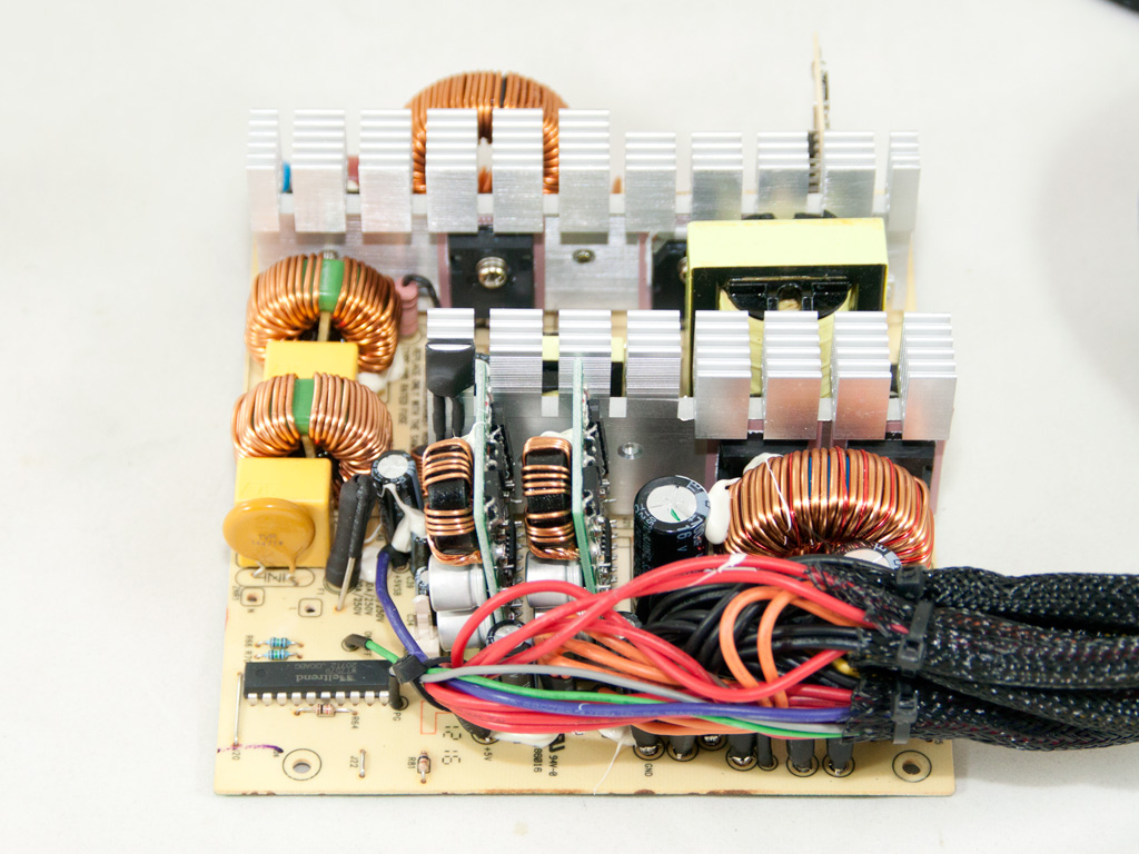
Two TK20J50D fets are used as main switchers. The combo PFC/PWM controller, a Champion CM6802 IC, resides on a vertical daughter-board. The latter is an upgraded version of the famous CM6800 found in numerous PSUs. The small transformer right in front of the vertical PCB is used for driving the main switchers.


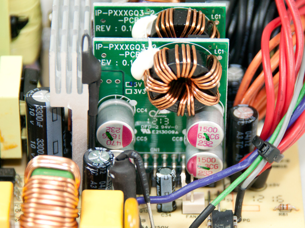


Four PFR40L60PT SBRs in the secondary side, passive components, rectify the +12V rail. The minor rails are generated by two DC-DC converters. Each consists of two pairs of M3016D and M3004D fets, and a uP3872B PWM controller, an IC for which we found no information on the net.


All filtering caps on the secondary side are electrolytic and are provided by Teapo. Teapo makes the best non-Japanese/Korean caps.

The supervisor IC taking care of all PSU protections is installed on the main PCB. It is a Weltrend WT7579 IC.

The standby PWM controller is installed on the component side of the main PCB. It is a TNY278PN IC.

The 5VSB rail is rectified by an STPS2045CT SBR.


Soldering quality is great. We also spotted the four current sense resistors, or shunts, that provide feedback to the OCP circuit here.

The cooling fan is provided by ADDA, and its model number is AD1212LB-A70GL (12 V, 0.24 A, 1400 RPM, 56 CFM, 28 dBA). It uses ball bearings and is, although it spins up to a relatively low RPM only, noisy at full speeds in our tests. That said, it is a highly reliable fan we usually only come across in more expensive units.
May 9th, 2024 13:54 EDT
change timezone
Latest GPU Drivers
New Forum Posts
- Your way of cooling your PC? (88)
- Only some humans can see refresh rates faster than others, I am one of those humans. (234)
- TPU's Nostalgic Hardware Club (18504)
- Battery swap for cyberpower UPS (66)
- Last game you purchased? (275)
- Current Sales, Bundles, Giveaways (10231)
- What's a good option for a digital touchless thermometer? (17)
- Epic Games launcher's ridiculous CPU usage (33)
- AM5 boot times improve RADICALLY with memory context restore enabled (1)
- Microsoft butchering Xbox Studios (26)
Popular Reviews
- CHERRY XTRFY M64 Pro Review
- Corsair iCUE Link RX120 RGB 120 mm Fan Review
- Bykski CPU-XPR-C-I CPU Water Block Review - Amazing Value!
- Finalmouse UltralightX Review
- Upcoming Hardware Launches 2023 (Updated Feb 2024)
- Corsair MP700 Pro SE 4 TB Review
- AMD Ryzen 7 7800X3D Review - The Best Gaming CPU
- Cougar Hotrod Royal Gaming Chair Review
- ASUS Radeon RX 7900 GRE TUF OC Review
- Meze Audio LIRIC 2nd Generation Closed-Back Headphones Review
Controversial News Posts
- Intel Statement on Stability Issues: "Motherboard Makers to Blame" (262)
- AMD to Redesign Ray Tracing Hardware on RDNA 4 (206)
- Windows 11 Now Officially Adware as Microsoft Embeds Ads in the Start Menu (167)
- NVIDIA to Only Launch the Flagship GeForce RTX 5090 in 2024, Rest of the Series in 2025 (144)
- Sony PlayStation 5 Pro Specifications Confirmed, Console Arrives Before Holidays (119)
- AMD's RDNA 4 GPUs Could Stick with 18 Gbps GDDR6 Memory (114)
- NVIDIA Points Intel Raptor Lake CPU Users to Get Help from Intel Amid System Instability Issues (106)
- AMD Ryzen 9 7900X3D Now at a Mouth-watering $329 (104)