 0
0
OCZ ZT Series 750 W Review
Voltage Regulation & Efficiency »A Look Inside
Before reading this page we strongly suggest to take a look at this article, which will help you understand the internal components of a PSU much better.

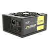
The OEM behind ZT units is Great Wall, the same manufacturer that makes the high-end ZX series for OCZ. The heatsinks look small for a Bronze PSU but they are quite thick so they will effectively remove the heat from the mosfets and the SBRs (Schottky Barrier Diodes). The design definitely is not modern since DC-DC converters are not utilized for the minor rails' generation, although in theory the high power of +12V indicated the opposite. Nevertheless we have independent regulation for the major rails so voltage regulation will not be affected. On the contrary, judging from our experience although DC-DC converters provide better efficiency in general, they fail to provide good voltage regulation, in most cases.
The transient filtering stage starts at the AC receptacle with one X and two Y caps. It continues on the main PCB with two CM chokes, one X and two Y caps. Unfortunately Great Wall, like they did in the ZX units, did not use an MOV (Metal Oxide Varistor). This is a negative point of course and this PSU should be used along with a surge protector.

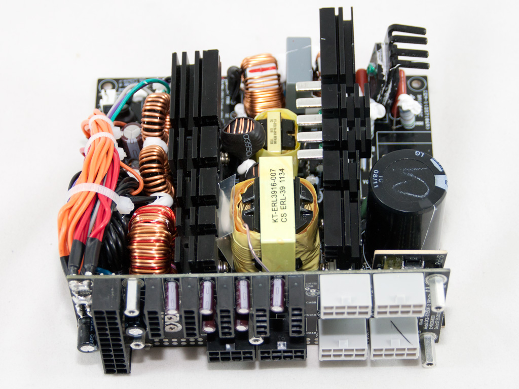
The two bridge rectifiers are bolted on a dedicated heatsink. Their model number is T15KB60and each can handle 15 Amps max. Right before and after the bridge rectifiers we find two X caps which provide high frequency ripple filtering.


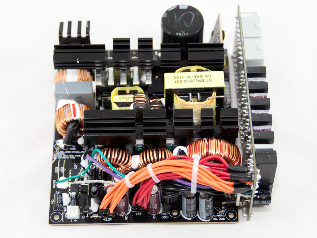
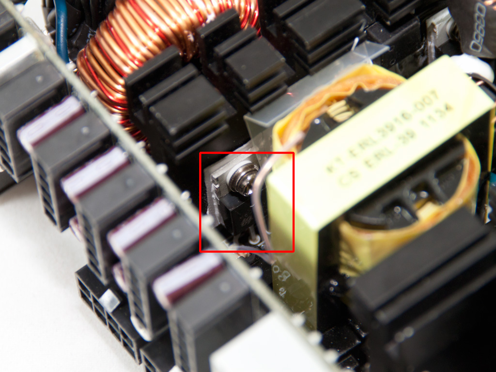
To give you a better view of the APFC mosfets, two SPW24N60C3, we removed the PFC sealed choke. As boost diode an LQA08TC600 is used. Right in front of the boost diode there is the thermistor that provides protection against large inrush currents.


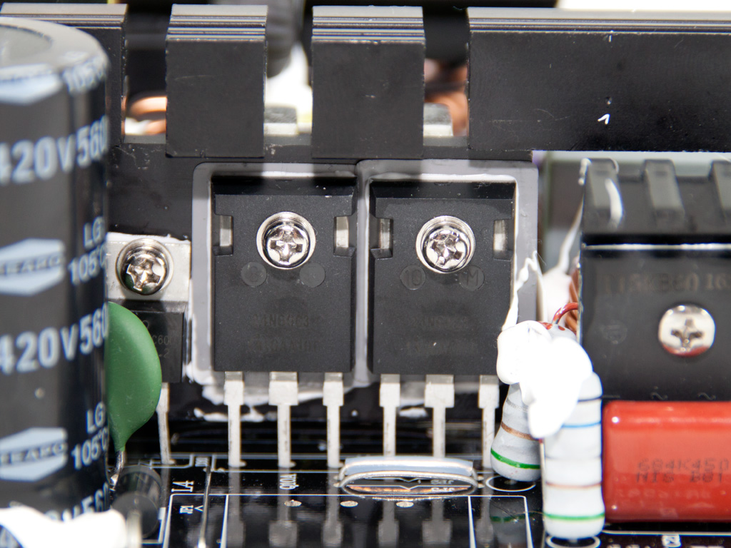
The hold up cap is provided by Teapo (560μF, 420V, 105°C). Next to it, the leaning PCB houses the combo PFC/PWM controller, the famous CM6800.

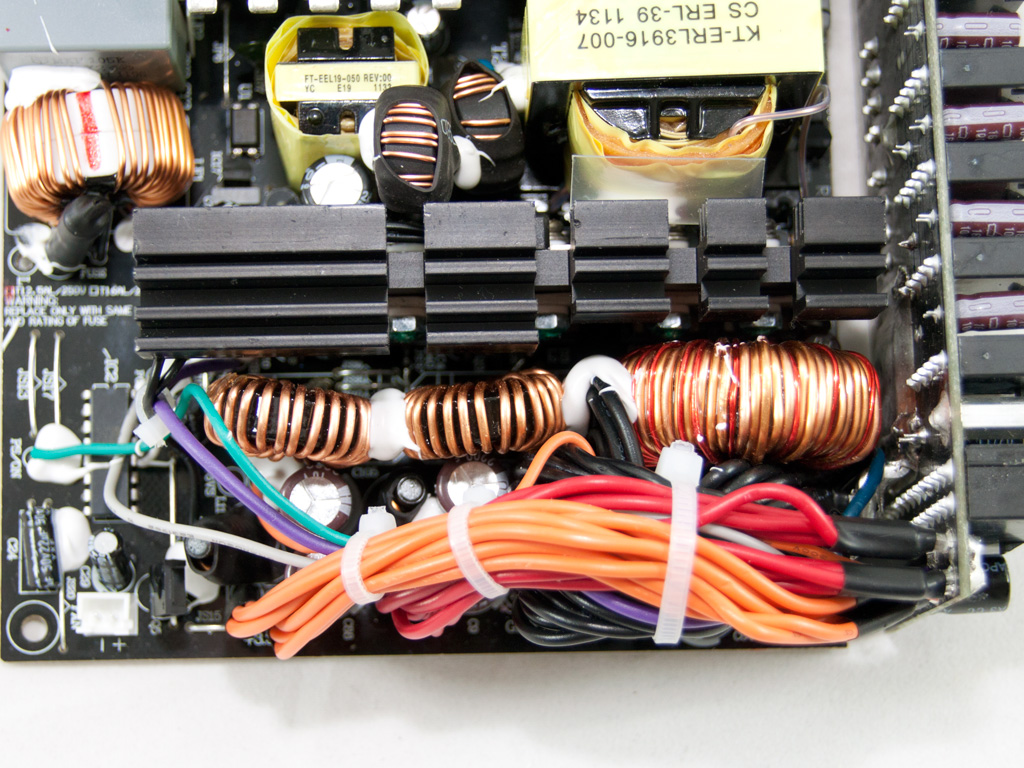
The main switches are two SPP20N60C3 fets. In the secondary, Semi Synchronous design is used since the +12V rail regulates four mosfets while 5V and 3.3V are generated by conventional SBRs. Also the presence of three toroidal chokes indicates that independent regulation is used. Strangely enough the coil that filters/rectifies 5V has exactly the same size as the one for 3.3V. Usually the former is larger than the latter but in this unit the 5V rail outputs fewer Amps than 3.3V so its max power is not much higher.


All capacitors used in the secondary side are provided by Nippon Chemi-Con and Rubycon. The +12V rail is transferred to the modular PCB through a bus bar, for minimized losses. Grounding is delivered to the modular PCB through a combination of several wires and a bus bar.
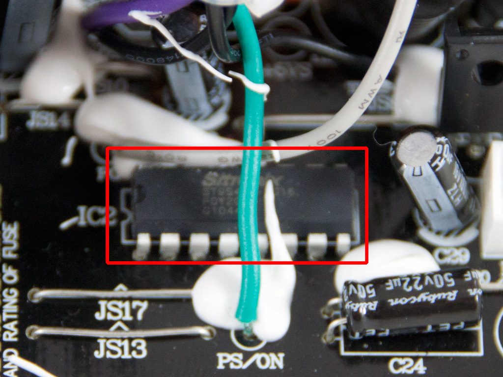

The protections IC is provided by Sitronix and its model number is ST9S424-PG16. Unfortunately we could not find any information about it on the web.
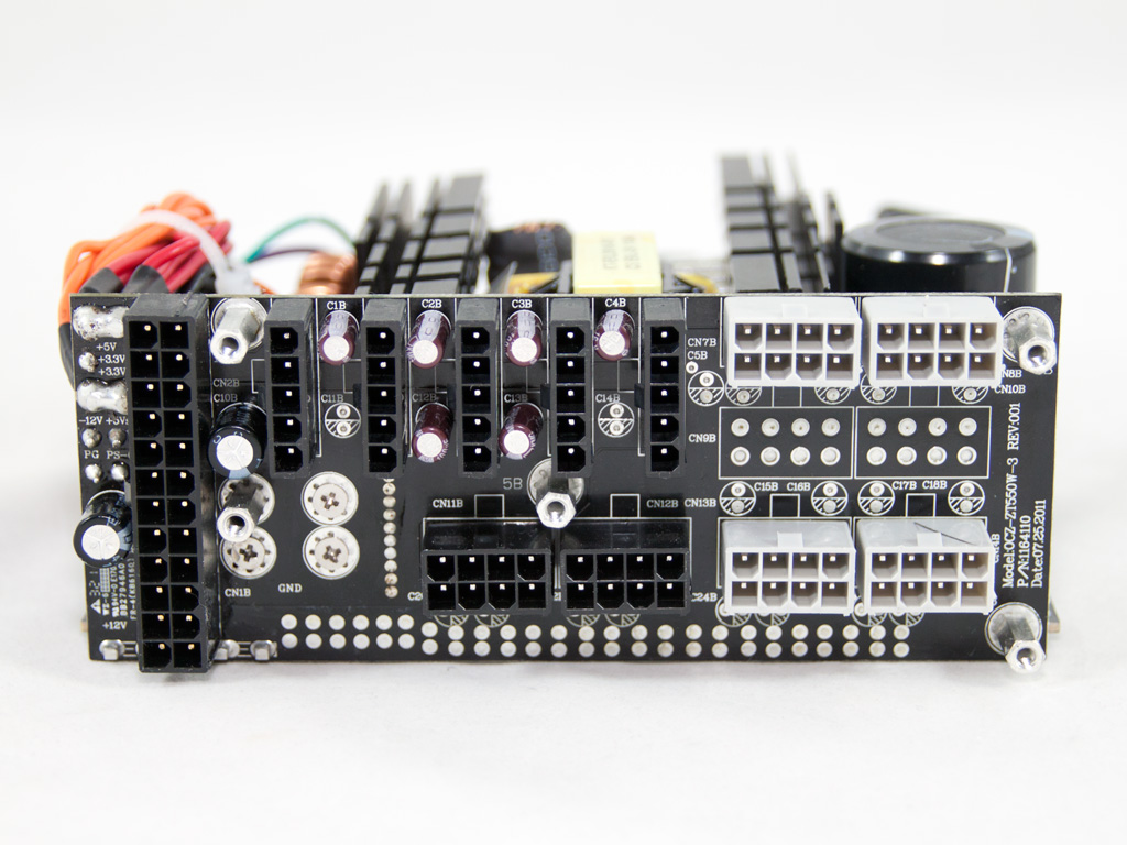
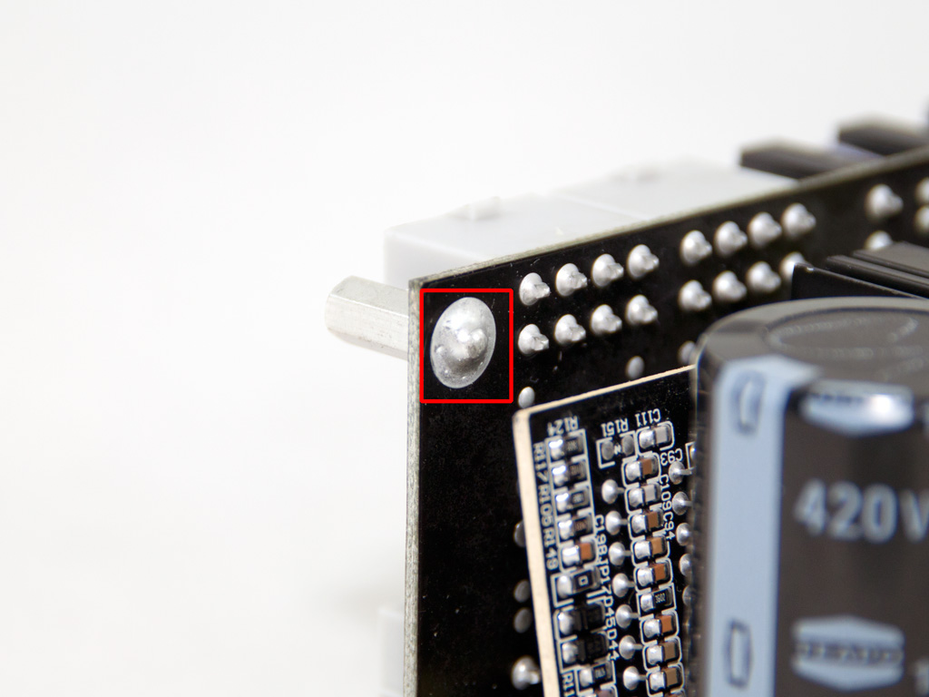

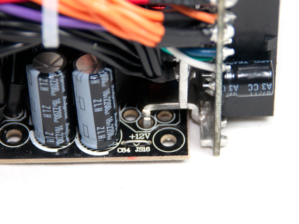
On the front of the modular PCB there are six Chemi-Con and two Teapo caps for some extra ripple filtering. There are void spaces for lots more but apparently OCZ decided that eight of them would be enough to handle ripple. Looking at the solder side of the modular PCB we noticed that the stand offs are not bolted but soldered. This is definitely not the smartest thing to do in a fully modular PSU but since five stand offs hold the PCB to the casing and the bus bars also provide enough rigidity, we believe there won't be any problems.
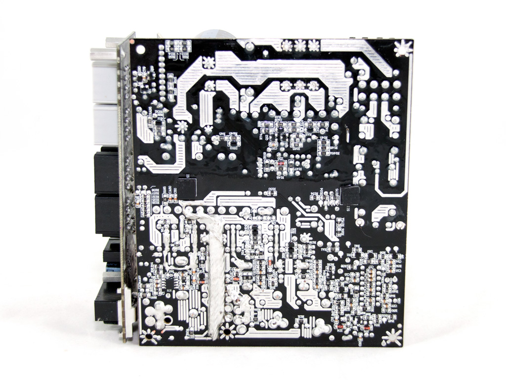


Soldering on the main PCB is quite good but there are some spots with sloppy solder joints. Notice the enhanced channel used for enchanced grounding, definitely not an eye candy. Finally, in the primary side we found a thick layer of protective coating.
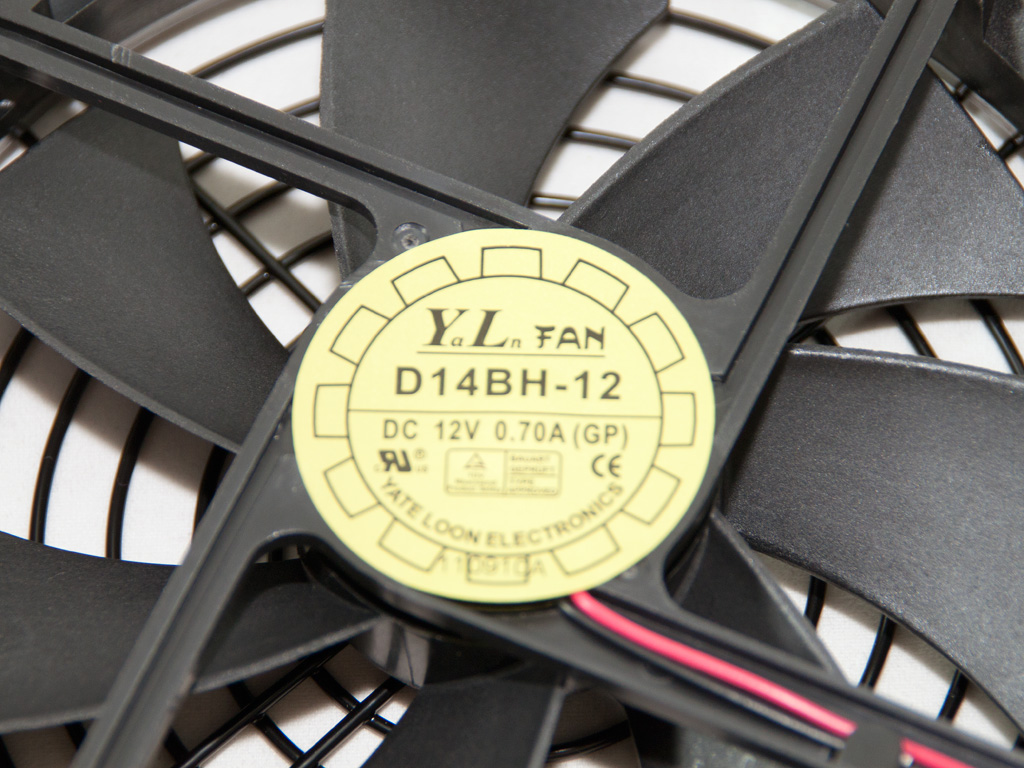
The cooling fan is provided by Yate Loon Electronics and its model number is D14BH-12 (2800 RPM, 140 CFM, 48.5 dB). It provides high airflow but its max noise output can be really annoying.
Apr 26th, 2024 17:23 EDT
change timezone
Latest GPU Drivers
New Forum Posts
- 5800x (and other Zen 3 chips) PBO settings/Temperature fix (934)
- Only EDP Other in Core? (2)
- What's your latest tech purchase? (20353)
- Alphacool CORE 1 CPU block - bulging with danger of splitting? (30)
- Dell Workstation Owners Club (3061)
- Xeon Owners Club (8700)
- Secure boot already open help (10)
- hacked (77)
- Best SSD for system drive (92)
- looking to build a new system and im considering asrock brand but i have some doubts/concerns. (4)
Popular Reviews
- HYTE THICC Q60 240 mm AIO Review
- MOONDROP x Crinacle DUSK In-Ear Monitors Review - The Last 5%
- Upcoming Hardware Launches 2023 (Updated Feb 2024)
- Alienware Pro Wireless Gaming Keyboard Review
- Thermalright Phantom Spirit 120 EVO Review
- FiiO K19 Desktop DAC/Headphone Amplifier Review
- ASUS Radeon RX 7900 GRE TUF OC Review
- AMD Ryzen 7 7800X3D Review - The Best Gaming CPU
- RTX 4090 & 53 Games: Ryzen 7 5800X vs Ryzen 7 5800X3D Review
- Sapphire Radeon RX 7900 GRE Pulse Review
Controversial News Posts
- Windows 11 Now Officially Adware as Microsoft Embeds Ads in the Start Menu (135)
- Sony PlayStation 5 Pro Specifications Confirmed, Console Arrives Before Holidays (117)
- NVIDIA Points Intel Raptor Lake CPU Users to Get Help from Intel Amid System Instability Issues (106)
- AMD "Strix Halo" Zen 5 Mobile Processor Pictured: Chiplet-based, Uses 256-bit LPDDR5X (103)
- US Government Wants Nuclear Plants to Offload AI Data Center Expansion (98)
- AMD's RDNA 4 GPUs Could Stick with 18 Gbps GDDR6 Memory (95)
- Developers of Outpost Infinity Siege Recommend Underclocking i9-13900K and i9-14900K for Stability on Machines with RTX 4090 (85)
- Windows 10 Security Updates to Cost $61 After 2025, $427 by 2028 (84)